




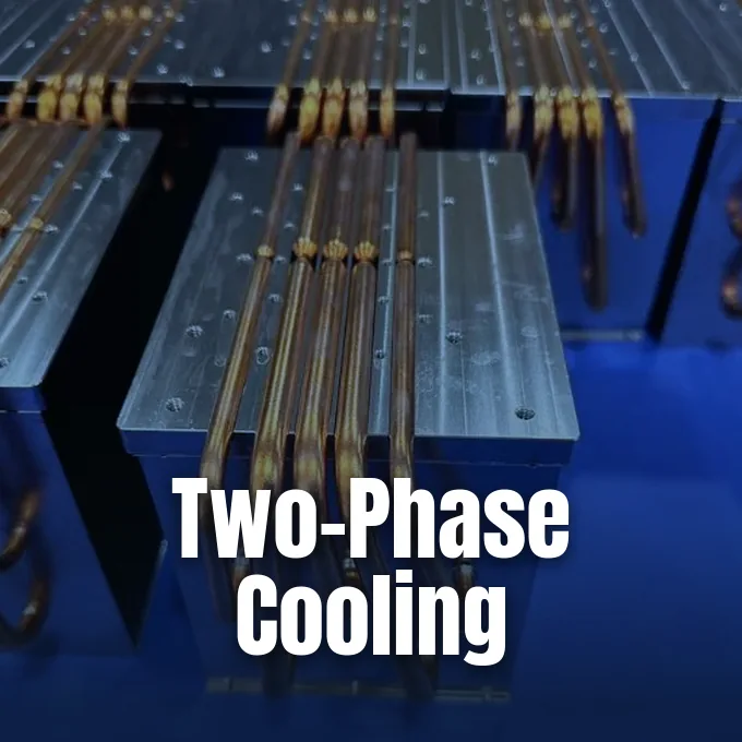
A heat pipe moves thermal energy away from hot surfaces by turning a liquid into vapor and condensing it at a cooler end. The core heat pipe working principle couples two-phase thermodynamic changes with capillary action inside a vacuum-sealed shell, transferring heat hundreds of times faster than solid copper [5]. Solid metal heat sinks rely on fixed conduction where heat spreads slowly through atom vibrations. In contrast, a two-phase pipe carries heat as moving mass, absorbing huge energy spikes at the heat source and venting that heat to remote cooling fins without requiring mechanical pumps or electrical power [7].
- The Heat Pipe Working Principle
- How Capillary Wicks Return Condensed Liquid
- Working Fluids for Specific Temperature Ranges
- Physical Limits That Constrain Heat Transport
- Vapor Chambers for Planar Heat Spreading
- How Do Loop Heat Pipes Work?
- Heat Pipe Working Principle in Electronics Cooling
- Aerospace and Nuclear Microreactor Applications
The Heat Pipe Working Principle
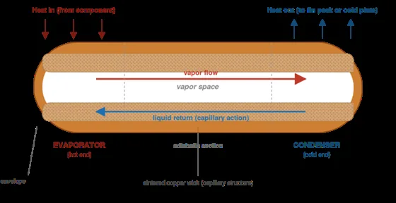
The sealed tube contains a porous wick lining its inner walls and a measured charge of working fluid held under a partial vacuum. Lowering the pressure inside the copper shell reduces the boiling point of the fluid, allowing de-ionized water to vaporize at normal room temperatures rather than waiting for one hundred degrees Celsius. When a processor or power transistor heats the evaporator section, the liquid trapped in the wick turns into steam. Water boasts an exceptionally high latent heat of vaporization of roughly 2,260 kJ/kg, which is about five times the thermal energy needed to heat the same volume from freezing to boiling. Solid copper conducts heat at roughly 400 W/m·K [5].
Rapid vaporization creates a localized pressure spike that pushes vapor through the hollow center of the pipe toward the condenser at speeds reaching hundreds of meters per second [5]. At the cold interface, the vapor contacts cooler metal surfaces attached to external cooling fins, condensing back into liquid and releasing its latent heat. The porous wick then draws the liquid back to the hot evaporator through capillary pressure, enabling an unbroken thermodynamic loop [7]. This cycle explains how heat pipes work to cool systems without moving parts while keeping temperature differences across the pipe exceptionally small. Effective thermal conductivity ranges from 1,500 to over 60,000 W/m·K, easily beating standard solid metals [5].
How Capillary Wicks Return Condensed Liquid
The capillary wick serves as the internal engine of the pipe, pumping condensed fluid back to the heat source without any external drive. Engineers balance two competing forces when selecting a wick: capillary pressure and permeability. Capillary pressure dictates how strongly the pore structure pulls liquid against gravity, while permeability governs how freely liquid moves through the porous layer without choking the return stream. Sintered powder metal wicks, formed by baking tiny copper spheres into a solid sponge, offer very small pore openings that generate high capillary force [7]. This strong pumping power allows laptops and server racks to run reliably in any orientation, even when the hot evaporator sits directly above the cold condenser [6].
Grooved wicks feature tiny parallel channels extruded directly into the inner copper wall. These open channels deliver outstanding permeability for high fluid volume, but their wide openings create very weak capillary lift [7]. Sintered wicks handle adverse angles much better than grooved tubing. In tests documented by Celsia, a standard eight-millimeter sintered water pipe transported roughly 127 W when assisted by gravity, 68 W in a horizontal orientation, and only 8 W when working against gravity in a vertical position [5]. Screen mesh wicks use woven metal wire rolled against the inner tube wall, providing a middle ground between cost and pumping capability. When severe thermal loads combine with tight spaces, composite wicks pair axial grooves with fine wire mesh to keep fluid flowing freely [7].
Working Fluids for Specific Temperature Ranges
Working fluids must remain in a liquid and vapor saturation state across the entire operating window of the target device. If the temperature falls below the freezing point of the fluid, the liquid solidifies and circulation stops. If the temperature climbs too high, all fluid turns to gas, vapor pressure spikes, and the pipe can’t condense the vapor back into the wick [12]. De-ionized water dominates electronics cooling between 20 °C and 150 °C because of its high surface tension and immense latent heat [6]. For freezing environments, engineers replace water with ethanol, which operates from -10 °C to 100 °C, or methanol, which handles temperatures down to -40 °C in cold aerospace avionics [5].
Envelope materials and working fluids must share strict chemical compatibility to avoid long-term decay. While copper pairs cleanly with water, combining aluminum envelopes with water causes chemical reactions that generate non-condensable hydrogen gas within days, blocking vapor from reaching the condenser [12]. Spacecraft and aerospace radiators rely on aluminum envelopes paired with anhydrous ammonia, which functions between -50 °C and 100 °C [5]. High-temperature industrial equipment and chemical ovens require fluids like naphthalene between 200 °C and 400 °C [6]. Above 500 °C, liquid alkali metals such as sodium and potassium provide the high thermal conductance needed to transfer thousands of watts without breaking down [12].
Physical Limits That Constrain Heat Transport
Every heat pipe operates within five classical boundaries that dictate its maximum heat transport capacity, known as Qmax [5]. The capillary limit represents the most common boundary in consumer hardware, occurring when the heat load evaporates fluid faster than the wick can draw liquid back from the condenser. When capillary forces fall short, the evaporator dries out, wall temperatures jump, and thermal runaway threatens the underlying silicon [7]. The boiling limit occurs when excessive local heat flux boils fluid violently inside the wick rather than at its surface, forming a vapor blanket that insulates the heat source [5].
Other boundaries emerge during startup or under extreme flow velocities. The sonic limit appears during cold startups when vapor reaches Mach 1 at the evaporator exit, choking mass flow and restricting heat transfer until temperatures rise. The entrainment limit occurs when high-velocity vapor strips returning liquid droplets off the wick surface, dragging fluid back toward the condenser and starving the evaporator [5]. The viscous limit restricts fluid circulation at very low temperatures where viscous drag dominates vapor movement [15]. Physical modifications also alter these limits; flattening an eight-millimeter tube down to narrow profiles or adding sharp bends reduces internal cross-sectional area, lowering overall Qmax [5].


Vapor Chambers for Planar Heat Spreading
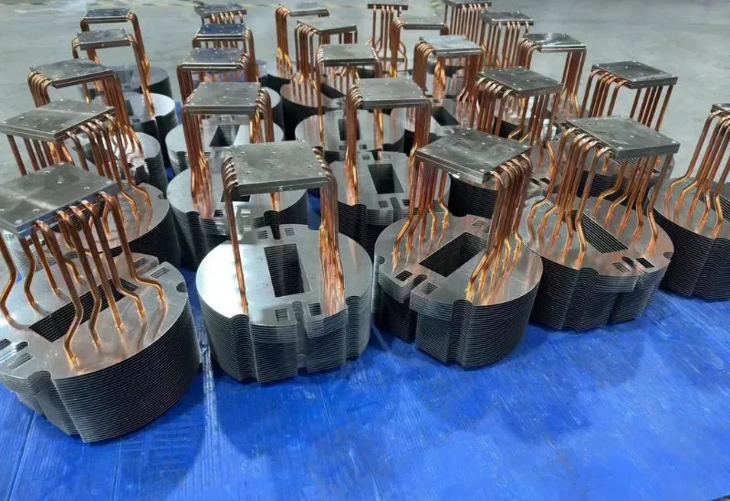
Vapor chambers apply the same heat pipe working principle across a flat, two-dimensional plate instead of a round tube. In high-power processors, heat concentrates on a small silicon die, creating intense local thermal flux that standard metal spreaders struggle to dissipate [5]. A vapor chamber attaches directly to the heat source, allowing vapor to expand outward in all directions toward a wide fin array [9]. Internal support columns and sintered copper pillars give the sealed chamber the mechanical rigidity needed to withstand clamping pressures up to 90 psi without collapsing the internal vapor core [12].
Flat cooling plates work well in thin mobile devices where vertical clearance is limited to a few millimeters. While tubular pipes excel at shuttling heat over longer distances to distant radiator fins, vapor chambers eliminate interface layers by serving as the direct baseplate of the cooling assembly [5]. Recent materials research explores replacing standard metal casings with lighter carbon structures. In an unreviewed preprint on arXiv, Liu and colleagues reported a graphene-enhanced heat pipe achieving a heat dissipation capacity of 6,100 W m-2 K-1 g-1, about three times higher than commercial copper pipes [2]. This development connects directly with broader graphene and heat conduction research that studies phonon scattering behavior in advanced nanomaterials [1].
How Do Loop Heat Pipes Work?
A loop heat pipe moves heat by separating vapor and liquid lines into distinct smooth-walled tubes, preventing high-velocity vapor from shearing returning liquid droplets. In a classic heat pipe, vapor and liquid travel in opposite directions inside a single tube, which creates shear stress and viscous drag along the wick surface. Loop designs solve this problem by confining the capillary wick entirely to the evaporator section. When heat vaporizes the fluid at the evaporator wick, vapor travels down an open vapor line to a remote condenser, while a dedicated liquid line routes condensate back to an adjacent compensation chamber [13].
The compensation chamber operates at a slightly lower temperature and saturation pressure than the evaporator, which continuously draws returning liquid back into the primary wick. Soviet engineers Yury F. Gerasimov and Yury F. Maydanik patented this loop architecture in 1974, securing a United States patent in 1982. Loop systems operate reliably over several meters and can pump fluid against gravity far more effectively than standard pipes. These capabilities made loop systems indispensable on orbital spacecraft, including the Granat satellite, Boeing HS 702 communications platforms, and NASA space shuttle flights STS-83 and STS-94. Terrestrial electronics also adopt loop configurations when heat sources sit far from chassis exhaust vents [13].
Heat Pipe Working Principle in Electronics Cooling
The origins of two-phase cooling date back to the steam age, when Angier March Perkins and Loftus Perkins developed gravity-fed Perkins tubes for locomotive boilers and baker’s ovens. Modern capillary heat pipes emerged in 1942 through a patent by R. S. Gaugler at General Motors, though practical development waited until 1963 when George Grover independently built working prototypes at Los Alamos National Laboratory. Grover coined the term heat pipe and recognized its immense potential for satellite cooling where gravity is absent. Commercial consumer electronics adopted the technology during the 1980s, when Sony began fitting copper heat pipes into audio amplifiers and stereo receivers to replace noisy fans [12].
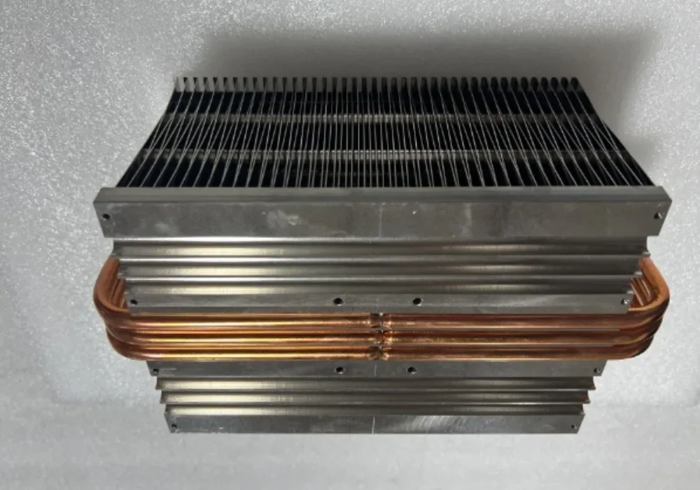
Today, desktop CPU coolers from manufacturers like Noctua use multiple nickel-plated copper pipes pressed against heat spreaders to shuttle thermal energy into dense aluminum fin stacks [9]. In thin laptops, engineers use flattened pipes down to thicknesses of less than one millimeter to cool central processors without adding bulk [6]. Radian Thermal Products showed that micro heat pipes with profiles down to 0.6 mm reach thermal equilibrium within 3 to 5 seconds, compared to 140 seconds for solid copper bars [8]. Furthermore, heat pipe systems in building HVAC units wrap around cooling coils to precool incoming humid air and reheat supply air passively, helping commercial facilities meet ASHRAE standard 90.1 energy rules [11].
Aerospace and Nuclear Microreactor Applications
Spacecraft face extreme thermal swings, absorbing intense solar radiation on one side while facing the deep cold of space on the other. Heat pipes equalize these temperature spikes across satellite transponders, distributing heat without consuming electrical power or relying on failure-prone mechanical pumps [12]. In propulsion research at the University of Central Florida, Wei Wu, Yeong Ren Lin, and Louis Chow integrated heat pipes into an air-cooled rotary Wankel engine designed for unmanned aerial vehicles. Their simulation showed that spreading heat dropped peak housing temperatures from 231 °C to 129 °C while shrinking temperature variations across the engine by 8.8 times, cutting thermal stress and mechanical warping [4].
Advanced nuclear engineering also harnesses two-phase heat transfer to build solid-state microreactors that eliminate coolant pumps, mitigating loss-of-coolant accidents. Microreactors like NASA’s Kilopower project and Westinghouse’s commercial eVinci system, planned for Malmstrom Air Force Base, use high-temperature alkali metal pipes operating above 900 K to carry fission heat directly to Stirling engines or gas turbines [14]. At Idaho National Laboratory, researchers working under the Department of Energy Microreactor Program test these systems using specialized non-nuclear test beds like SPHERE and the 250-kW MAGNET facility [3, 16]. These high-temperature pipes demonstrate that the same passive thermodynamic cycle cooling a laptop can safely extract heat from a nuclear core [10].
- ACADEMIC JOURNAL Liu, Y., Chen, S., Fu, Y., Wang, N., Mencarelli, D., Pierantoni, L., Lu, H., & Liu, J. (2020). A lightweight and high thermal performance graphene heat pipe. Nano Select, 2(2). [Article Link]
- PREPRINT Liu, Y., Chen, S., Fu, Y., Wang, N., Mencarelli, D., Pierantoni, L., Lu, H., & Liu, J. (2020). A light-weight and high thermal performance graphene heat pipe. arXiv:2002.11336. [Article Link]
- REPORT Qin, S., Nunez, III, L., Sellers, Z., Hartvigsen, J., Sabharwall, P., Thompson, S., Reid, R., Petrov, V., Seo, J., Hassan, Y., & Bardet, P. (2022). Advanced Measurement and Visualization Techniques for High-Temperature Heat Pipe Experiments. Idaho National Laboratory. [Article Link]
- CONFERENCE PAPER Wu, W., Lin, Y. R., & Chow, L. (2014). A Heat Pipe Assisted Air-Cooled Rotary Wankel Engine For Improved Durability, Power And Efficiency. SAE Technical Papers, 2014-September. [Article Link]
- WEBSITE Demars, M. (2019). How Do Heat Pipes Work? Heat Pipes 101: Construction, Working Principle, and Performance. Celsia. [Article Link]
- WEBSITE KenFa Tech. (2025). Heat Pipes: The Ultimate Guide to Efficient Thermal Management. KenFa Tech. [Article Link]
- WEBSITE Walmate Thermal. (2025). Heat Pipes Explained: An Engineer’s Guide to How They Work. Walmate Thermal. [Article Link]
- WEBSITE Radian Thermal Products. (2016). How do Copper Heat Pipes Work? Radian Thermal Products, Inc. [Article Link]
- WEBSITE McClements, D. (2023). Heat Pipe: Definition, Components, Types, Applications, and Factors That Affect Its Performance. Xometry. [Article Link]
- WEBSITE GALLOP INNOTEK. (2026). What is the Heat Pipe? — A Complete Guide. GALLOP INNOTEK. [Article Link]
- WEBSITE Heat Pipe Technology. (2025). Heat Pipe Principle and Applications. Heat Pipe Technology, Inc. [Article Link]
- WEBSITE Wikipedia contributors. (2026). Heat pipe. Wikipedia, The Free Encyclopedia. [Article Link]
- WEBSITE Wikipedia contributors. (2026). Loop heat pipe. Wikipedia, The Free Encyclopedia. [Article Link]
- WEBSITE Wikipedia contributors. (2026). Heat pipe-cooled reactor. Wikipedia, The Free Encyclopedia. [Article Link]
- ACADEMIC JOURNAL Faghri, A. (2012). Review and Advances in Heat Pipe Science and Technology. ASME Journal of Heat and Mass Transfer, 134(12). [Article Link]
- ACADEMIC JOURNAL Sabharwall, P., Hartvigsen, J. L., Morton, T. J., Yoo, J., Qin, S., Song, M., Guillen, D. P., Unruh, T., Hansel, J. E., Jackson, J., Gehin, J., Trellue, H., Mascarenas, D., Reid, R. S., & Petrie, C. M. (2023). Nonnuclear Experimental Capabilities to Support Design, Development, and Demonstration of Microreactors. Nuclear Technology, 209(sup1), S41-S59. [Article Link]


