






Heat moves naturally from warm zones to cool zones, but solid metal slabs often struggle to spread sharp thermal loads across tight computer frames. A sealed hollow pipe solves this thermal bottleneck by circulating an internal fluid that boils at the heat source and condenses at the cooler end. The physics behind how heat pipes work reveals how passive phase changes transport high thermal loads at speeds up to hundreds of times faster than solid copper conductors without using motors, fans, or external power cords. These sealed metal tubes operate as self-contained thermodynamic circuits that move heat smoothly across minimal temperature drops. They keep critical components cool while operating silently for decades [1].
How Heat Pipes Work in Modern Hardware
George Grover independently built capillary-driven heat pipes at Los Alamos National Laboratory in 1963, coining the name to describe his sealed heat transfer invention. Grover realized that closed two-phase evaporation circuits could carry reactor heat out into space radiators without needing fragile mechanical pumps. Decades earlier, in 1942, R. S. Gaugler of General Motors had patented a capillary pipe idea, but Gaugler never built a working hardware model. Even earlier, Angier March Perkins and his son Loftus Perkins built gravity-driven Perkins Tube systems during the steam age to warm locomotive boilers and bakery ovens. Grover turned those raw concepts into reliable spaceflight hardware. Studying how heat pipes work in early aerospace programs showed that phase transitions could move heat without electricity [1].
NASA engineers adopted Grover’s prototypes in the 1960s to protect orbiting communications satellites from solar extremes. Spacecraft faced blazing solar heat on one side while their shadow side plunged into freezing space. Variable-conductance heat pipes balanced those satellite hulls without drawing electrical power [1].
Sony introduced heat pipes into commercial stereo amplifiers during the 1980s to replace noisy cooling blowers. Microcomputer processor heat spiked in the late 1990s, causing patent applications to triple across personal computer makers. Pure copper rods conduct about 0.4 kW/(m⋅K), but long heat pipes reach an effective thermal conductivity near 100 kW/(m⋅K) under steady operation [1].

Phase Change Inside the Vapor Core
A standard heat pipe consists of three distinct functional zones along its sealed metallic shell: an evaporator, an adiabatic transport section, and a cooling condenser. Thermal energy from a hot component conducts through the outer metal wall into the evaporator zone. Saturated liquid held within an internal porous wick absorbs this thermal energy and boils into vapor at constant saturation temperature. That latent heat of vaporization lets modest amounts of working fluid soak up large quantities of thermal energy without causing any measurable rise in fluid temperature. Boiling vapor expands swiftly into the open core of the sealed tube, establishing a continuous flow path. The underlying thermodynamic cycle of how heat pipes work depends on this continuous vaporization process absorbing concentrated heat spikes from chips at constant saturation temperature [1].
Vapor flows rapidly along the central void because the adiabatic zone presents almost zero hydraulic resistance. At the far end, cooler walls in the condenser zone cause the vapor to condense back into liquid film. A pipe two feet long and one inch wide can move 3.7 kW at 980 °C with only a 10 °C drop. Peak designs handle heat fluxes exceeding 23 kW/cm² [1].
Heat pipes fail if temperatures move outside operational design boundaries. Cold temperatures freeze the liquid so it cannot boil, while extreme heat turns all fluid to gas and halts condensation [1]. Researcher A. Faghri reported in the ASME Journal of Heat and Mass Transfer that industrial plants build millions of heat pipes each month for computer cooling [2].
Wick Structures for Liquid Return
Liquid return from the cold condenser to the heat source requires reliable pumping force without moving parts. The porous wick lining the inner casing provides this passive return through capillary action. Capillary pressure inside the wick explains how heat pipes work against gravitational drag during vertical operation. Menisci formed inside tiny wick pores generate the suction needed to draw fluid forward [1].
Engineers select wick materials based on the balance between capillary pumping power and liquid permeability. Sintered copper powder wicks feature very small pore diameters, producing powerful capillary suction that allows heat pipes to function upside down or through sharp bends. Axial grooved wicks cut directly into copper tubing provide lower friction for liquid return over long straight runs, but grooved channels lose pumping power when tilted upward. Woven wire screen meshes offer an intermediate balance, giving manufacturers a flexible option for simple commercial heat sinks. Proper wick thickness keeps liquid supplied to the evaporator without blocking heat transfer through the metal shell [1].

Liquid friction inside the porous wick accounts for most flow resistance in capillary heat pipes. In a numerical modeling study published in Frontiers of Energy Research, researcher Y. Guo and colleagues analyzed a 1.0 m high-temperature pipe, finding that pressure drop in the wick reached 8,422.47 Pa. By comparison, vapor space pressure drop was only 896.68 Pa. Vapor flow created just 2.6 K of the total 31.7 K temperature difference along the pipe. Wick permeability governs maximum heat transfer limits [12].
Working Fluids in Heat Pipes
Working fluids must match the temperature limits of each cooling system [1]. In a broad review in Energy, H. Jouhara and colleagues detailed how operating temperatures dictate working fluids and shell pairings [3]. Fluids must possess high latent heat, chemical stability, and appropriate saturation pressures across expected thermal swings [1].
Cryogenic instruments on space telescopes use liquid helium between 2–4 K, while nitrogen and neon function below 100 K. Room-temperature hardware relies on ammonia operating between 213 K and 373 K, methanol between 283 K and 403 K, or water between 298 K and 573 K. High-temperature systems use liquid metals, with mercury operating from 523 K to 923 K and sodium from 873 K to 1473 K. Liquid indium serves specialized industrial crucibles at extreme ranges from 2000 K to 3000 K. A mismatched fluid stops boiling entirely, cutting heat transport down to simple metallic wall conduction [1].
Standard consumer hardware pairs copper casings with pure water [1]. In a survey in Applied Thermal Engineering, M. J. Gibbons and colleagues examined ultra-thin flat heat pipes used in foldable mobile devices like the Samsung Galaxy Fold and Huawei Mate X. Thin vapor chambers spread heat across flexible hinges where internal clearance measures under a millimeter [4].


Corrosion Risks and Gas Buildup
Heat pipe shells and internal fluids must remain chemically inert together through years of thermal cycling. If a fluid reacts with its metal casing, chemical decomposition generates non-condensable gas inside the sealed volume. As vapor flows toward the cooling sink, it pushes these gas molecules to the far tip of the condenser. Over time, trapped gas pockets block working vapor from touching cold metal surfaces, cutting the active condensing area and causing evaporator temperatures to rise sharply. Chemical compatibility tests ensure that envelopes and working liquids do not produce gas under sustained heat loads [1].
Water placed inside an aluminum casing creates a disastrous pairing. Aluminum oxidizes in the presence of water, generating non-condensable hydrogen gas within hours. The hydrogen bubble blankets the condenser, choking heat flow until efficiency falls to roughly 1/80 of design capacity. Aluminum tubes require anhydrous ammonia instead [1].
Factories run endurance trials to monitor corrosion and internal gas formation over thousands of continuous hours. Careful chemical cleaning before sealing removes manufacturing oils that could decompose into gas. Copper and water pairings deliver stable operation across decades of electronics cooling [1].
Loop Designs in Space Vehicles
Standard heat pipes face physical hurdles when carrying thermal loads over long distances or against adverse gravity slopes. Dense wicks create heavy friction when liquid travels along the entire tube length, producing large pressure losses. Outbound vapor also shears against returning liquid, causing entrainment losses that starve the evaporator of fluid. Examining how heat pipes work across long distances reveals why conventional designs suffer from wick friction [6].
Soviet inventors Yury F. Gerasimov and Yury F. Maydanik solved these distance limitations in 1974 by patenting the loop heat pipe under inventor’s certificate No. 449213, later securing a United States patent in 1982. Loop heat pipes confine the capillary wick exclusively to the evaporator chamber, leaving the separate vapor and liquid lines as smooth, wickless transport tubes. A two-phase compensation chamber attached to the evaporator operates at a slightly lower saturation temperature, creating pressure differences that draw returned liquid into the core wick. This layout permits flexible tubing runs that snake around obstacles without losing pumping power [6].
Loop heat pipes first flew into space aboard a Russian spacecraft in 1989. Since that flight, aerospace builders have used loop systems to cool commercial satellites, including Boeing HS 702 platforms, the Russian Granat and Obzor spacecraft, and the Chinese FY-1C weather satellite. NASA tested loop heat pipes during space shuttle missions STS-83 and STS-94 in 1997 [6]. Researcher K. N. Shukla noted in the Journal of Electronics Cooling and Thermal Control that loop systems handle high heat loads over long runs while resisting adverse gravitational forces [5].
Pulsating Tubes in Industrial Recovery
During the 1990s, inventor Hisateru Akachi developed pulsating heat pipes that operate without any internal wick structures. Researcher Sameer Khandekar explained in Electronics Cooling that a pulsating heat pipe consists of a plain meandering capillary tube bent into parallel U-turns. The tube is partially filled with working fluid that naturally settles into alternating liquid slugs and vapor bubbles. Thermal gradients between hot and cold zones create pressure imbalances that push these fluid plugs back and forth in an oscillating motion. Akachi’s Kenzan Fin module transferred heat an order of magnitude better than solid metal cooling fins [7].
Large two-phase thermosyphons protect Arctic infrastructure by keeping underlying permafrost frozen year-round. As software developer Simmakers Ltd. documented, vertical tubes filled with carbon dioxide, ammonia, or propane pull heat out of foundation soil during winter. Subterranean evaporators boil liquid, vapor rises to outdoor radiator fins, and cold winter air condenses the fluid so gravity carries it back down [8].

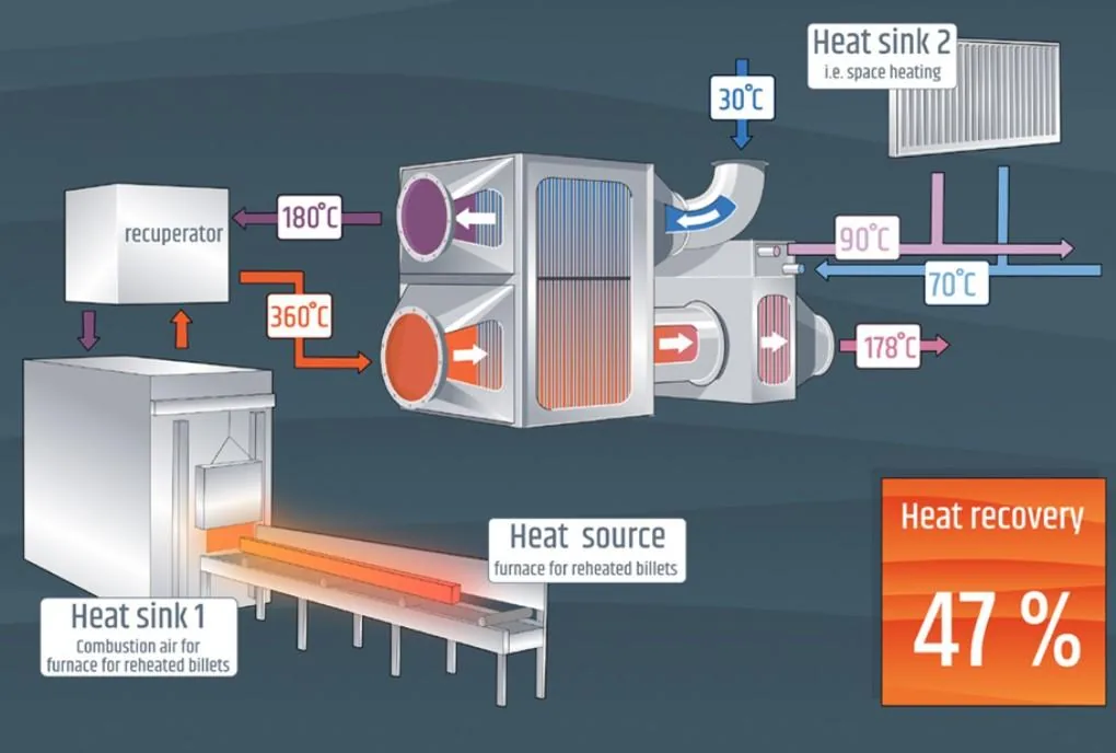
Factories also use heat pipe exchangers to recover waste heat from high-temperature exhaust stacks. Between 2017 and 2022, the European Union backed the ETEKINA project with €4,617,680 of its €5,539,610 budget. Coordinated by IKERLAN S. COOP in Arrasate-Mondragón, Spain, engineers placed exchangers in steel, aluminium, and ceramics factories in Spain, Italy, and Slovenia. Installed in 2021, these systems recovered over 40% of exhaust waste heat, achieving technology readiness level TRL7 [9].
Nuclear Cores and Graphene Heat Pipes
Nuclear designers use heat pipes to cool compact microreactors passively, eliminating coolant pumps and preventing loss-of-coolant accidents. Modern microreactors prove how heat pipes work under high temperatures to keep core fuels stable without active pumps. On September 13, 2012, NASA and the US Department of Energy demonstrated the DUFF test, producing 24 W of electricity from a reactor core using heat pipes and a stirling engine. In 2018, the 5 kWth KRUSTY prototype sustained core temperatures exceeding 800 °C during a full-day operational run. Westinghouse is now developing the eVinci microreactor for deployment at Malmstrom Air Force Base by 2030 [10].
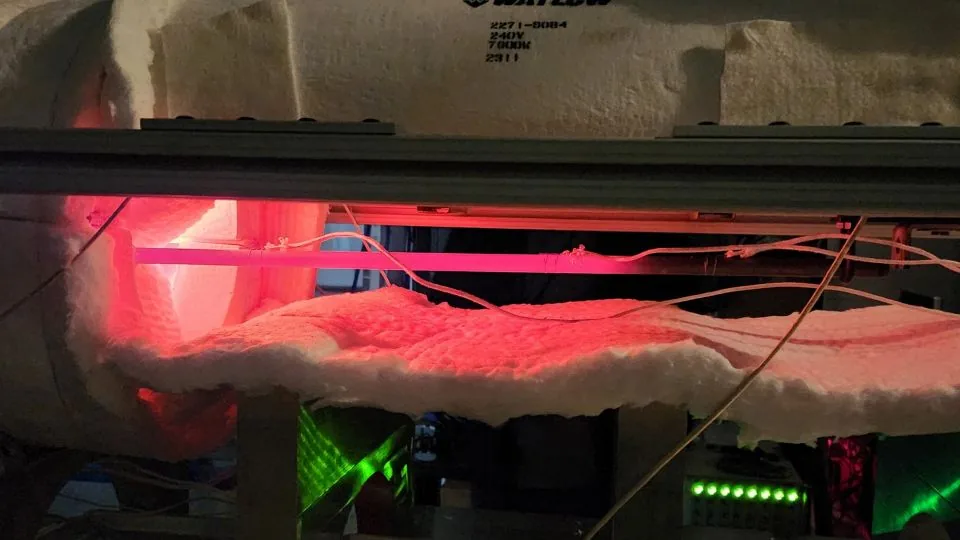
At Idaho National Laboratory, researchers Ilyas Yilgor, Mauricio Tano, Katrina Sweetland, Joshua Hansel, and Piyush Sabharwall completed a ranking study for microreactor heat pipes under the DOE Microreactor Program, observing sodium tubes glowing at ~800 °C in the SPHERE facility [11]. In propulsion, researchers Wei Wu, Yeong Ren Lin, and Louis Chow embedded heat pipes into an air-cooled Wankel rotary engine. Writing in the SAE Technical Paper Series, the team reported that their test dropped peak housing temperatures from 231 °C to 129 °C, cutting temperature non-uniformity by 8.8 times [13].
In 2020, Y. Liu and colleagues developed graphene heat pipes to reduce hardware weight in aerospace and handheld electronics [14, 15]. Their initial paper was released as an unreviewed preprint on arXiv [14]. In peer-reviewed results published in Nano Select, their graphene design achieved a heat dissipation capacity of 7,230 W m⁻² K⁻¹ g⁻¹, roughly 3.5 times higher than copper pipes [15]. Meanwhile, D. M. Weragoda and colleagues reviewed heat pipe cooling for electric vehicle battery packs in Applied Thermal Engineering [16].
- WEBSITE Wikipedia. (n.d.). Heat pipe. [Article Link]
- ACADEMIC JOURNAL Faghri, A. (2012). Review and Advances in Heat Pipe Science and Technology. ASME Journal of Heat and Mass Transfer, 134(12). [Article Link]
- ACADEMIC JOURNAL Jouhara, H., Chauhan, A., Nannou, T., Almahmoud, S., Delpech, B., & Wrobel, L. C. (2017). Heat pipe based systems – Advances and applications. Energy, 128, 729-754. [Article Link]
- ACADEMIC JOURNAL Gibbons, M. J., Marengo, M., & Persoons, T. (2021). A review of heat pipe technology for foldable electronic devices. Applied Thermal Engineering, 194, 117087. [Article Link]
- ACADEMIC JOURNAL Shukla, K. N. (2015). Heat Pipe for Aerospace Applications—An Overview. Journal of Electronics Cooling and Thermal Control, 05(01), 1-14. [Article Link]
- WEBSITE Wikipedia. (n.d.). Loop heat pipe. [Article Link]
- ONLINE NEWS Khandekar, S. (2003). An Introduction to Pulsating Heat Pipes. Electronics Cooling. [Article Link]
- WEBSITE Simmakers Ltd. (2013). Thermosyphon Technology for Ground Freezing. [Article Link]
- REPORT European Climate, Infrastructure and Environment Executive Agency. (2025). ETEKINA. [Article Link]
- WEBSITE Wikipedia. (n.d.). Heat pipe-cooled reactor. [Article Link]
- ONLINE NEWS Yilgor, I., Tano, M., Sweetland, K., Hansel, J., & Sabharwall, P. (2025). The current status of heat pipe R&D. Nuclear News. [Article Link]
- ACADEMIC JOURNAL Guo, Y., Su, Z., Li, Z., Wang, K., & Liu, X. (2022). An Improved Model of the Heat Pipe Based on the Network Method Applied on a Heat Pipe Cooled Reactor. Frontiers in Energy Research, 10. [Article Link]
- CONFERENCE PAPER Wu, W., Lin, Y., & Chow, L. (2014). A Heat Pipe Assisted Air-Cooled Rotary Wankel Engine for Improved Durability, Power and Efficiency. SAE Technical Paper Series, 1. [Article Link]
- PREPRINT Liu, Y., Chen, S., Fu, Y., Wang, N., Mencarelli, D., Pierantoni, L., Lu, H., & Liu, J. (2020). A light-weight and high thermal performance graphene heat pipe. arXiv:2002.11336. [Article Link]
- ACADEMIC JOURNAL Liu, Y., Chen, S., Fu, Y., Wang, N., Mencarelli, D., Pierantoni, L., Lu, H., & Liu, J. (2020). A lightweight and high thermal performance graphene heat pipe. Nano Select, 2(2). [Article Link]
- ACADEMIC JOURNAL Weragoda, D. M., Tian, G., Burkitbayev, A., Lo, K. H., & Zhang, T. (2023). A comprehensive review on heat pipe based battery thermal management systems. Applied Thermal Engineering, 224, 120070. [Article Link]
Cover image: KaiBorgeest / Wikimedia Commons, CC BY 4.0


