





Learning how optical fibers work starts with a simple physical trick. Instead of moving electrical charges through copper wire, these hair-thin glass strands guide pulses of light across long distances [1]. The light acts as an optical carrier wave, transporting digital internet traffic with minimal loss [3].
- Principles of Light Guidance in Glass
- How Optical Fibers Work With Total Reflection
- Single-Mode Versus Multimode Core Designs
- Signal Attenuation Boundaries
- Light Sources With Fast Detectors
- Subsea Cable Systems and How Optical Fibers Work
- Mechanical Connectors in Field Infrastructure
- Wavelength Multiplexing and How Optical Fibers Work
Principles of Light Guidance in Glass
Light moves in straight paths until it hits a boundary between two transparent substances. When a light ray passes from a dense medium into a rarer medium, it bends away from the normal line according to Snell’s law until reaching the critical angle. Why does light stay inside transparent glass instead of escaping into open air? If the angle of incidence exceeds the critical angle, the ray cannot cross the boundary and reflects back completely. Addanki, Amiri, and Yupapin review optical fibers as cylindrical dielectric waveguides in Results in Physics, explaining how light confinement relies on this refractive contrast [2]. To see how optical fibers work, engineers study how light reflects at this boundary.
Every glass line contains two layers with distinct optical densities. In 1954, Harold Hopkins and Narinder Singh Kapany in Britain showed that bundles of glass strands could guide light images across complex curves, laying early groundwork for optical waveguides [3]. The high-index core sits in the center, completely wrapped by a lower-index cladding so that incoming light rays reflect inward along the inner wall instead of escaping into the surrounding buffer. Total internal reflection creates a mirror effect without any metal coating. Glass traps the light [2].
Light does not stop abruptly at the boundary between core and cladding during reflection. A decaying electromagnetic field, called an evanescent wave, penetrates a fraction of a wavelength into the lower-index cladding layer before turning back toward the core. Sensor designers use this boundary interaction for measurement. Researchers build fiber Bragg gratings (FBGs) and long-period gratings that track surface refractive index changes by monitoring how biological analytes alter this evanescent wave. Chiavaioli, Baldini, Tombelli, Trono, and Giannetti show in Nanophotonics that these grating sensors achieve label-free chemical detection. Their spectral shifts respond to molecular interactions at the glass boundary without requiring bulky laboratory equipment [2].
How Optical Fibers Work With Total Reflection
Light must enter the glass strand at specific angles to stay trapped. The acceptance cone defines the angular range that undergoes total internal reflection, calculated by engineers through the numerical aperture (NA) of the fiber to prevent light from leaking into the cladding. Rays outside this cone vanish [5].
Early experiments in the 1960s struggled with heavy signal loss in glass lines. In 1963, Jun-ichi Nishizawa at Tohoku University proposed using glass fibers for optical communication. Common optical glass lost roughly 1,000 dB/km, which extinguished light pulses within meters. In 1966, Charles K. Kao and George Hockham at Standard Telecommunication Laboratories showed that impurities caused this loss, predicting that pure silica could drop attenuation below 20 dB/km [3]. Beginning in 1967, a research team at Corning Glass Works set out to reach that benchmark. Robert Maurer, Donald Keck, and Peter Schultz achieved the breakthrough in 1970 by producing a fused silica strand with attenuation low enough for communication. Corning Inc led commercial production. By 1982, improved chemical refinement extended this transmission distance to 125 kilometers before requiring signal regeneration [7].
How do manufacturers produce glass rods with such extreme purity? Modern factories rely on chemical vapor deposition methods to assemble optical preforms before drawing them into hair-thin strands. Technicians use modified chemical vapor deposition (MCVD) to react gaseous silicon tetrachloride and oxygen inside a rotating hollow silica tube under regulated industrial heating conditions. Germanium dopants are added in controlled amounts to raise the refractive index of the central core layer. Once the deposition finishes, the tube collapses into a solid glass preform rod. Drawing towers then heat the preform and pull it down into a continuous strand with a standard 125-micrometer outer diameter [2].
Single-Mode Versus Multimode Core Designs
When examining how optical fibers work over short runs, core size matters. Multimode optical fibers use a wide core that allows many spatial modes to propagate down the glass line. Standard multimode cores measure 50 to 62.5 micrometers in diameter, which makes aligning connectors and light sources straightforward. However, different light rays take different paths. Rays entering the wide core at steep angles reflect back and forth more often than rays traveling straight down the center, arriving slightly later at the far end. Modal dispersion limits the transmission distance because these overlapping paths cause optical pulses to spread apart as they travel toward the receiver [4].
Single-mode fiber avoids pulse spreading by narrowing the core to between 8 and 10 micrometers. Only the fundamental optical mode can propagate through this tight strand. Modal dispersion disappears completely. Single-mode lines support massive bandwidth-distance products, serving as the standard choice for long-distance telecommunications networks [4].

Cabling standards define performance categories for both fiber architectures. Standard ISO 11801 classifies multimode lines into OM1, OM2, OM3, and OM4 tiers, while standard G.651.1 sets parameters for 50/125-micrometer glass [4]. In 1977, General Telephone and Electronics deployed the first commercial optical telephone link between Long Beach and Artesia in California, using early LED sources at 6 Mbit/s [3]. VCSELs run at 850 nanometers. Laser-optimized OM3 and OM4 lines carry 100 Gb/s traffic across data halls, while standard TIA-598C assigns yellow jackets to single-mode cables and orange, aqua, or violet jackets to multimode cables [4].
Signal Attenuation Boundaries
Even pure glass lines lose some light as signals travel over long distances. Rayleigh scattering from microscopic density fluctuations in the fused silica accounts for most of this natural loss. In modern single-mode optical fiber, attenuation drops to approximately 0.2 dB/km at a wavelength of 1550 nanometers. At that low loss rate, a light pulse loses only around 5 percent of its optical power after traveling one full kilometer through the glass core. Coaxial copper cables lose electrical signal strength much faster and require repeaters every kilometer, but optical fiber networks operate with repeater spacings of up to 80 kilometers. This transmission advantage lets telecommunications providers span entire regions with few amplifiers [6].
Chromatic dispersion poses a separate physical challenge on high-speed transmission links. Because silica glass has a wavelength-dependent refractive index, slightly different colors of infrared light travel at slightly different group velocities along the central core. Distributed feedback (DFB) semiconductor lasers minimize this pulse broadening by emitting a narrow optical spectrum at 1550 nanometers [5]. In long-haul routes, digital coherent receivers use fast digital processors to equalize chromatic dispersion and polarization-mode dispersion directly in the electronic domain [13].
Pushing optical networks to higher capacities exposes physical boundaries in conventional silica glass. Mitch Jacoby notes in Chemical & Engineering News that while silica glass performs well, optical signals suffer distortion when light intensity reaches nonlinear thresholds. To support higher power levels and new transmission windows, material scientists formulate fibers based on fluoride glasses, polymers, and crystalline compound semiconductors. For instance, Sparks, He, Healy, and Peacock demonstrated zinc selenide semiconductor waveguides inside optical fibers with losses under 1 dB/cm at 1550 nanometers. This development expands options beyond conventional silica [1].



Light Sources With Fast Detectors
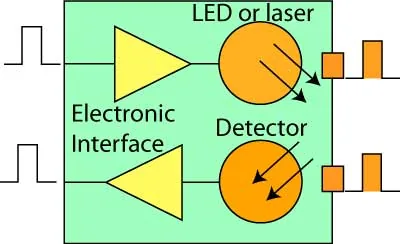
The way optical fibers work in high-speed links depends on fast light sources and receivers. In 1973, Gordon Gould co-founded Optelecom and won an ARPA defense contract in Huntsville, Alabama, to build fiber guidance for missiles before supplying Chevron with commercial links [3]. Transmitters use semiconductor chips that couple photons into the fiber core. Engineers choose between light-emitting diodes (LEDs), Fabry-Perot lasers, distributed feedback lasers, and VCSEL chips. LEDs offer low manufacturing costs but provide limited bandwidth below 250 MHz, so they work only in short links. Distributed feedback lasers emit high-power monochromatic beams at 1550 nanometers with superior linearity for dense wavelength-division multiplexing [5].
Photodetectors convert light pulses back into electrical currents. Silicon photodiodes handle short wavelengths like 650 nanometers for plastic fiber and 850 nanometers for glass. For long single-mode routes operating between 1310 and 1550 nanometers, receivers rely on indium gallium arsenide (InGaAs) photodetectors because InGaAs chips produce far less noise than germanium detectors to achieve high receiver sensitivity across long spans. Fast links add avalanche photodiodes. These diodes supply internal gain under high bias voltage [5].
Data modulation determines how many digital bits each light pulse carries down the glass strand. Simple datalinks use binary on-off keying, switching the laser on for a 1 and off for a 0, but direct modulation hits practical limits around 25 Gb/s. PAM4 modulation uses four pulse heights, allowing each optical symbol to carry two bits of data instead of one [5]. A single laser running PAM4 delivers 100 Gb/s throughput without multiplying hardware costs. While guided glass lines dominate telecommunications networks, unguided optical systems like LiFi technology and how light pulses transmit data through open air explore short-range wireless lighting setups.

Subsea Cable Systems and How Optical Fibers Work
Optical communication has deep roots. In 1880, Alexander Graham Bell and Charles Sumner Tainter created the Photophone at Volta Laboratory in Washington, D.C., transmitting speech over 213 meters on a sunbeam [3]. Telegraph operators originally crossed oceans using heavy copper cables laid along sea floors. In 1988, AT&T, Standard Telephones and Cables, and Submarcom deployed TAT-8, the first transatlantic telephone cable to use optical fibers across deep waters. It replaced copper lines. By 2000, marine crews had laid more than 300,000 miles (500,000 km) of fiber cables across oceans [7].
Deep-sea fiber cables require protective layers to shield delicate glass strands from ocean pressures and external hazards. Inside the cable, optical fibers sit inside a protective steel tube surrounded by high-strength steel wires and a copper power conductor that feeds submerged optical amplifiers. Near shorelines, heavy iron wire armoring protects the cable from ship anchors and fishing trawlers before specialized plows bury the line beneath sediment [7]. Subsea telecommunication cables rest on ocean floors worldwide, where research projects like underwater internet cables help biologists track whales by detecting acoustic vibrations along marine routes. By using optical fibers as acoustic sensors, scientists listen to marine life across entire ocean basins without deploying separate hydrophone arrays.
Subsea fiber installations expanded rapidly as global internet traffic exploded. By 2002, telecommunication carriers completed an intercontinental network encompassing 250,000 kilometers of submarine communications cables with an aggregate capacity of 2.56 Tb/s across transatlantic and transpacific corridors [3]. According to the International Telecommunication Union, internet usage reached 4.13 billion people by 2019, representing 53.6 percent of the world population [15]. By 2020, network operators had deployed more than 5 billion kilometers of optical fiber cable worldwide [3]. These undersea and terrestrial glass arteries now transport the vast majority of international telecommunications and digital data [7].
Mechanical Connectors in Field Infrastructure
Joining glass strands requires mechanical precision because misalignments of one micrometer cause optical attenuation. Field installations show how optical fibers work under outdoor stress when connecting distribution lines. Connectors link optical fibers where connect and disconnect capability is needed, avoiding permanent fusion splicing. Ceramic ferrules press polished glass endfaces into direct contact, eliminating signal losses from air gaps [8].
Modern data centers running cloud workloads require unprecedented port density inside equipment racks. US Conec, based in Hickory, North Carolina, engineered the MMC connector to answer these high-density networking demands in hyperscale facilities. The MMC design combines a reduced-size TMT ferrule with a very small form factor housing, delivering low insertion loss while providing three times the cabling density of traditional MPO connectors [9]. Standard IEC 61753-1 grades connector insertion loss from grade A to D and return loss from grade 1 to 5, ensuring that connector plugs withstand 500 to 1,000 mating cycles without signal degradation. Precise connector parts protect fragile glass cores during routine maintenance [8].

Deploying optical fibers in outside plant environments exposes hardware to harsh moisture, dust, and temperature fluctuations. Telcordia specification GR-1081 Issue 02 outlines generic requirements for field-mountable optical fiber connectors used in telephone central offices and customer premises [10]. For aerial, buried, and pedestal enclosures supporting fiber-to-the-premises rollouts, Telcordia standard GR-3120 Issue 02 defines requirements for hardened fiber optic connectors and adapters operating under environmental stress. These hardened connectors withstand mechanical tension and chemical exposure while delivering reliable subscriber drop links to optical network terminals [11]. Major global manufacturers like CommScope in North Carolina, Fujikura Ltd in Tokyo, YOFC in Wuhan, Belden Inc., Hengtong, and Sterlite Technologies in Pune supply matching cabling hardware [15].
Wavelength Multiplexing and How Optical Fibers Work
Wavelength-division multiplexing revolutionized optical communications during the 1990s by multiplying the information capacity of a single glass fiber. Instead of sending one signal at a time, transmitters combine dozens of laser beams at slightly different optical wavelengths into a single strand. At the receiving terminal, optical filters separate the individual wavelengths and route each channel to its own photodetector. Agrawal chronicles in Optics in Our Time how WDM deployment satisfied explosive internet demand without requiring telecommunications carriers to lay new transcontinental physical cabling lines [12].
Coherent optical communication represents another major leap in transmission efficiency. Early optical systems used simple direct detection that measured only the intensity of arriving light pulses. As reviewed by Kikuchi, digital coherent receivers mix incoming optical signals with a local oscillator laser to recover both optical amplitude and optical phase. Digital coherent technology enables spectrally efficient modulation formats such as quadrature amplitude modulation while tracking polarization states. High-speed digital processors compensate for linear impairments in real time, allowing single-mode fiber links to transmit terabits of data per second across thousands of kilometers. By combining advanced modulation formats with digital equalization, coherent transceivers overcome signal degradation and maximize the carrying capacity of installed undersea and terrestrial cables [13].
As standard single-core optical fibers approach the non-linear Shannon capacity limit, researchers are turning toward space-division multiplexing (SDM). Puttnam, Rademacher, and Luis report in Optica that SDM multiplies transmission capacity by utilizing multicore fibers and few-mode fibers within a single cladding diameter [14]. Novel multicore cables contain multiple independent light-guiding cores sharing the same protective coating, while coupled-core architectures process optical signals jointly. Laboratory demonstrations combining wavelength multiplexing, space multiplexing, and advanced coherent modulation have achieved data transmission rates exceeding 11 petabits per second across specialized fiber strands [6].
- ONLINE NEWS Jacoby, M. (2025). As telecom demands grow, optical fibers will need to level up. Chemical & Engineering News, 98(10). [Article Link]
- ACADEMIC JOURNAL Addanki, S., Amiri, I. S., & Yupapin, P. P. (2018). Review of optical fibers-introduction and applications in fiber lasers. Results in Physics, 10, 743-750. [Article Link]
- WEBSITE Wikipedia contributors. (n.d.). Fiber-optic communication. [Article Link]
- WEBSITE Wikipedia contributors. (n.d.). Multi-mode optical fiber. [Article Link]
- WEBSITE The Fiber Optic Association. (1999). Fiber Optic Transmitters and Receivers (Transceivers). [Article Link]
- ONLINE NEWS v Sivers, M. (2021). A Brief History Of Optical Communication. Hackaday. [Article Link]
- WEBSITE Smithsonian Institution Libraries. (2001). The Underwater Web: Cabling the Seas. [Article Link]
- WEBSITE Wikipedia contributors. (n.d.). Optical fiber connector. [Article Link]
- WEBSITE US Conec. (2026). MMC Connector Solutions. [Article Link]
- REPORT Telcordia Technologies. (2010). Generic Requirements for Field-Mountable Optical Fiber Connectors (GR-1081-CORE, Issue 2). [Article Link]
- REPORT Telcordia Technologies. (2010). Generic Requirements for Hardened Fiber Optic Connectors (HFOCs) and Hardened Fiber Optic Adapters (HFOAs) (GR-3120-CORE, Issue 2). [Article Link]
- BOOK CHAPTER Agrawal, G. P. (2016). Optical Communication: Its History and Recent Progress. Optics in Our Time, 177-199. [Article Link]
- ACADEMIC JOURNAL Kikuchi, K. (2015). Fundamentals of Coherent Optical Fiber Communications. Journal of Lightwave Technology, 34(1), 157-179. [Article Link]
- ACADEMIC JOURNAL Puttnam, B. J., Rademacher, G., & Luis, R. S. (2021). Space-division multiplexing for optical fiber communications. Optica, 8(9), 1186-1186. [Article Link]
- ONLINE NEWS Novicio, T. (2020). 15 Largest Fiber Optic Companies in the World. Yahoo! Finance. [Article Link]


