




Learning how CAN bus works reveals how vehicle electronics share data without a central computer. Robert Bosch GmbH began designing the Controller Area Network in 1983 to replace point-to-point wiring harnesses that added excess weight to road vehicles [6]. On this shared two-wire line, every connected node broadcasts sensor readings to the whole bus. Hardware filters inside each device inspect incoming ID tags, letting nodes process relevant bytes while discarding unneeded traffic [4]. The protocol coordinates vehicle subsystems through balanced differential voltages and bitwise arbitration, delivering sensor data deterministically even when multiple ECUs transmit at once [6].
- How CAN Bus Works: Origins and Development?
- Physical Layer and Differential Signaling
- How CAN Bus Works to Resolve Conflicts?
- Structure of the Four Message Frames
- Fault Confinement in Network Controllers
- How CAN Bus Works in Modern Vehicles?
- Higher Speeds With CAN-FD Technology
- Security Deficits in Vehicle Networks
How CAN Bus Works: Origins and Development?
Car makers in the early 1980s faced growing assembly problems as passenger vehicles adopted separate electronic modules for fuel injection, dashboards, and cabin environmental controls. Bosch engineers developed a serial network that could connect these isolated modules along a common communication pathway. The German company presented the CAN protocol in Detroit at the 1986 Society of Automotive Engineers conference, showing how multiplexed signals could replace thick bundles of dedicated copper wiring [6]. Chipmakers like Intel and Philips built dedicated silicon controllers to support the standard [4], [6]. Intel introduced the first CAN controller chip, the 82526, in 1987, and Philips developed its 82C200 controller shortly afterward [4],. Production adoption arrived when Mercedes-Benz installed the first multiplex wiring system in its flagship W140 saloon in 1991 [6].
Bosch updated the architecture in 1991 by releasing the CAN 2.0 specification. This release split the standard into two parts [6]. Part A defines standard frames with an 11-bit ID, while Part B specifies extended frames with a 29-bit ID [4],. The International Organization for Standardization adopted the protocol in 1993 as ISO 11898 [6].
Emissions rules cemented the protocol into global manufacturing. The United States mandated OBD-II diagnostic ports on cars starting in model year 1996, selecting CAN as an approved interface. The European Union enacted EOBD rules for petrol cars in 2001 and diesel engines in 2004 [6]. Early computers used parallel 32-bit buses like CardBus or Mostek 4096 DRAM memory traces, but serial lines proved far more rugged in engine bays [5], [6], [7]. While industrial racks used CompactPCI and VMEbus connected Motorola 68000 line of CPUs, CAN replaced legacy RS-232 serial interfaces with a noise-resistant differential backbone [1], [5], [7].
Physical Layer and Differential Signaling
At the physical layer, high-speed CAN networks operate under ISO 11898-2, sending data over a balanced pair of copper wires labeled CAN_H and CAN_L [4], [6]. When the bus sits idle, drivers hold both lines at about 2.5 volts, producing a zero-volt difference that signifies a recessive logical 1. To transmit a dominant logical 0, a driver drives CAN_H toward 3.5 volts and pulls CAN_L toward 1.5 volts, generating a 2.0-volt differential across the pair [4]. Because external electrical noise strikes both conductors equally, the receiver subtracts incoming noise cleanly. This differential design shows how the bus works reliably near spark plugs, heavy alternators, and 48-V commercial trailer test systems [1], [3].
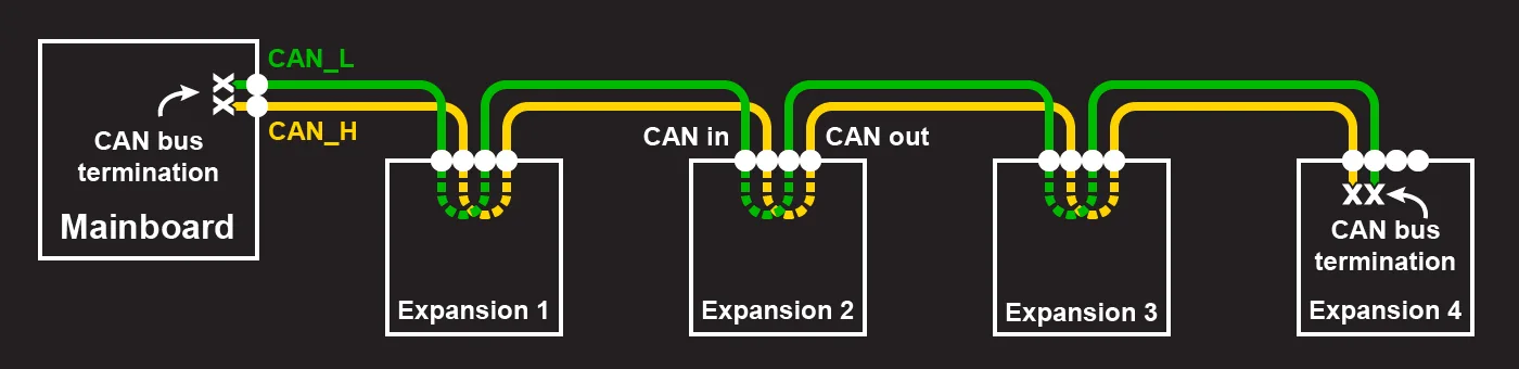
Bus termination prevents electrical reflections that corrupt bit edges. High-speed backbones require a 120-ohm resistor at each physical end of the cable. These resistors match the characteristic cable impedance. Without termination, signals bounce off open cable ends and create destructive echoes [1].
Copper cables restrict data transfer rates over distance. At the standard rate of 1 Mbit/s, the total cable distance between the two farthest nodes cannot exceed 40 meters. Lowering the speed to 500 kbit/s lets builders stretch lines to about 80 meters. Motion platforms like Duet 3 hardware use modular RJ11 connectors similar to standard Ethernet jacks and twisted-pair lines like Lapp 0035101, limiting drop stubs to 1 meter [1]. Vehicular systems rely on 9-pin D-sub connectors, where pin 2 carries CAN-Low, pin 7 carries CAN-High, pin 3 provides ground, and drivers withstand jump-start surges reaching 24 volts in cars and 36 volts in heavy trucks [6].

How CAN Bus Works to Resolve Conflicts?
Because CAN is a broadcast bus, every node hears every frame transmitted on the line. Senders do not specify destination addresses. Instead, each frame begins with an arbitration ID that describes the payload data. Local message filters in each node inspect this header tag, allowing chips to capture relevant data while ignoring unneeded messages. When multiple ECUs detect an idle line and transmit at the same time, the network resolves the conflict using bitwise arbitration without corrupting data [4].
The protocol uses Non-Return to Zero encoding with a strict bit-stuffing rule. Whenever a sender outputs five consecutive bits of the same logic level, hardware automatically inserts an opposite bit into the stream. The bus acts like a wired-AND gate, meaning dominant zero bits always overwrite recessive one bits [4].
Arbitration happens bit by bit as nodes transmit their message IDs onto the wire. Each sending chip reads the line voltage during its own transmission. If a node outputs a recessive 1 but senses that the bus is dominant at logical 0, it realizes that a higher-priority message is claiming the channel. The node ceases transmission right away and switches into listening mode without corrupting the winning frame. Because dominant zeros win every contest, smaller binary ID numbers carry higher priority. For example, an emergency brake packet with ID 100 wins arbitration over an air conditioning command with ID 234, showing how the bus works to deliver safety data without delay [4], [6].
Structure of the Four Message Frames
The CAN specification standardizes four message frames to handle regular data delivery, polling requests, error notifications, and transceiver pauses. The most common type is the Data Frame, which carries real-time measurements from sensors to recipient nodes. In standard CAN 2.0A, a Data Frame begins with a single dominant Start of Frame bit, followed by an 11-bit ID and a dominant Remote Transmission Request bit. Extended CAN 2.0B expands this identifier to 29 bits by inserting Substitute Remote Request and Identifier Extension bits. Kvaser technical documentation notes that this 29-bit address space allows complex heavy vehicles and industrial machines to organize message priorities across hundreds of distinct functions [4].
After the ID field, a 4-bit Data Length Code specifies how many payload bytes follow, ranging from 0 to 8 bytes. The payload is protected by a 15-bit Cyclic Redundancy Check field and a recessive CRC delimiter. Next comes the Acknowledgement Slot. Every listening node that decodes the frame without detecting a calculation error drives the bus dominant during this bit, confirming proper reception to the sending controller [4]. Seven recessive bits mark the end of the frame, followed by a 3-bit interframe intermission [2], [4].
The remaining three frame types govern special operational states. A Remote Frame carries a recessive RTR bit without payload data, prompting another node to reply with a matching Data Frame. An Error Frame transmits six identical dominant bits to destroy a faulty packet [4]. In a 2009 technical brief, author Kop explained that busy controllers like the Intel 82526 used Overload Frames during interframe spaces to delay incoming traffic [2], [4].

Fault Confinement in Network Controllers
High network reliability in noisy operating environments depends on autonomous error detection built into controller silicon [4],. The protocol enforces five distinct checking mechanisms: bit monitoring, bit stuffing checks, frame formatting checks, acknowledgement verification, and cyclic redundancy checksums [8]. Bit monitoring requires sending drivers to read back the bus level continuously during transmission. If a driver outputs a dominant bit but reads a recessive voltage outside arbitration, it flags an immediate bit error [4].
Controllers isolate hardware failures using two internal registers: the Transmit Error Counter and the Receive Error Counter. Successful packet transmissions decrease these counter tallies, while detected errors increase them. Under ISO 11898-1, these numeric counts determine which of three operational health states the node occupies [4].
Under normal operating conditions, a healthy node remains in the Error Active state. An active node signals any detected corruption by driving six dominant bits onto the bus, forcing all other controllers to discard the flawed transmission. If a node suffers intermittent connection faults and its transmit counter climbs past threshold limits, it enters the Error Passive state. In passive mode, the node may still send and receive messages, but it signals detected errors using eight recessive bits rather than dominant ones. If continuous hardware faults push the counter beyond the cutoff limit, the controller switches into the Bus Off state, disconnecting its transmitter electrically so broken hardware cannot paralyze the rest of the vehicle [4].
How CAN Bus Works in Modern Vehicles?
Modern road vehicles operate as distributed computing networks, frequently containing up to 70 electronic control units that communicate over shared CAN lines [6], [8]. Rather than installing dedicated wiring between every separate sensor and motor, vehicle systems exchange digitized messages. For example, auto start-stop features combine sensor inputs from wheel speed, steering angle, engine temperature, and climate control to determine whether shutting down the engine at traffic lights will improve fuel economy without making the passenger cabin uncomfortably warm [6].
Cross-system data sharing coordinates complex convenience and chassis mechanisms. Electric park brakes consult vehicle tilt sensors, wheel speeds, and seat belt latch switches over the CAN bus, holding brake pressure on steep hills and releasing automatically when the driver accelerates away. When reverse gear engages, transmission controllers broadcast a notification that tilts passenger side mirrors downward toward the curb and activates ultrasonic bumper sensors. High-performance Audi and BMW vehicles use rain sensor signals to pulse antilock brake calipers imperceptibly during highway rainstorms, wiping moisture films off brake discs to keep stopping distances short. For less time-sensitive cabin hardware like power windows, automakers often pair CAN with slower LIN sub-buses [6].
Telemetry illustrates how the bus works outside traditional road cars [1], [6],. In an uncontrolled study of 54 drivers over 2,000 trips, researchers Fugiglando, Massaro, and Santi analyzed pedal and steering signals to cluster driver behaviors [14]. Commercial applications also link Shimano DI2 bicycle derailleurs introduced in 2009, Duet 3 toolboards on CNC machines and 3D printers, roboRIO modules in FIRST Robotics, and Johns Hopkins Modular Prosthetic Limb servos [1], [6].

Higher Speeds With CAN-FD Technology
As advanced driver assistance systems proliferated, traditional CAN bandwidth became a limiting factor for automotive designers. Bosch introduced CAN-FD in 2012 to address this constraint. Flexible Data-Rate technology lets controllers increase data throughput without abandoning established bus topology. The core concept of overclocking the payload had originated at Bosch in 1999 [8].
CAN-FD achieves higher performance by decoupling the arbitration phase from payload delivery. During arbitration, the bus operates at standard speeds up to 1 Mbit/s, letting nodes resolve message priorities across long physical cables. Once a transmitter wins the bus, it asserts the Bit Rate Switch bit and accelerates clock timing, transmitting payload data at rates between 5 Mbit/s and 8 Mbit/s. In addition to higher bit rates, CAN-FD expands maximum payload capacity from 8 bytes up to 64 bytes per frame. Transmitting larger payloads within a single message header reduces protocol overhead significantly, showing how the bus works to stream high-resolution sensor packets far more efficiently [8].
CRC checksums expand to protect longer data payloads. CAN-FD employs a 17-bit CRC checksum for payloads up to 16 bytes, and a 21-bit CRC sequence for payloads between 17 and 64 bytes. Network engineers apply De Andrade’s equation based on Tindel’s formula to model bus loads under dynamic bit-rate switching [8]. The CAN in Automation consortium continues evolving these standards into CAN XL, testing high-speed physical layers and CANsec security protocols at engineering expos in Nuremberg and Shanghai [3].
Security Deficits in Vehicle Networks
Early vehicle networks functioned as closed electronic systems, operating without connections to external computing devices [6],. Consequently, original CAN specifications omitted message encryption, sender authentication, and authorization checks [9], [10]. Because the bus relies on open broadcast signaling, any device wired to the harness can listen to all traffic and inject unauthorized packets [9], [10]. As modern vehicles added cellular modems, Bluetooth interfaces, and third-party OBD-II diagnostic dongles, this lack of cryptographic defense exposed in-vehicle controllers to remote attack surfaces [9], [10].
Security researchers like Bozdal and Lokman have documented several common attack patterns against automotive buses [9], [13]. In a Denial of Service attack, a rogue node broadcasts continuous zero-ID frames to monopolize arbitration and starve legitimate nodes [10], [12]. In fuzzing attacks, injected random payloads trigger controller crashes [10], [12]. Spoofing attacks forge valid sensor readings to manipulate dashboard displays or steering behavior [9], [10], [12].
To mitigate vulnerabilities without rewiring existing fleets, automakers deploy intrusion detection systems [9], [10], [11], [13]. A research study published in IEEE Access by Hossain demonstrated an anomaly detector using Long Short-Term Memory neural networks, successfully classifying injected DoS, fuzzing, and spoofing attacks on real car data [10]. Another approach developed by Hanselmann, the CANet deep learning architecture, detects irregular transmission timing across high-dimensional message streams without requiring labeled attack datasets [11]. Combining anomaly detection with CAN SIC transceivers and emerging CANsec hardware security modules helps automotive engineers protect passenger safety while preserving deterministic microsecond bus response times [3], [9].
- WEBSITE Duet3D Documentation. (2021). CAN connection basics. [Article Link]
- WEBSITE Kop. (2009). CAN BUS MESSAGE FRAMES – Overload Frame,Interframe Space. [Article Link]
- WEBSITE CAN in Automation. (2026). CAN in Automation (CiA). [Article Link]
- WEBSITE Kvaser. (2026). CAN Bus Protocol Tutorial. [Article Link]
- WEBSITE PinoutGuide. (2025). Computer buses and slots connectors pinouts. [Article Link]
- WEBSITE Wikipedia. (n.d.). CAN bus. [Article Link]
- WEBSITE Wikipedia. (n.d.). Bus (computing). [Article Link]
- WEBSITE Wikipedia. (n.d.). CAN FD. [Article Link]
- ACADEMIC JOURNAL Bozdal, M., Samie, M., Aslam, S., & Jennions, I. K. (2020). Evaluation of CAN Bus Security Challenges. Sensors, 20(8), 2364. [Article Link]
- ACADEMIC JOURNAL Hossain, M. D., Inoue, H., Ochiai, H., Fall, D., & Kadobayashi, Y. (2020). LSTM-Based Intrusion Detection System for In-Vehicle Can Bus Communications. IEEE Access, 8, 185489-185502. [Article Link]
- ACADEMIC JOURNAL Hanselmann, M., Strauss, T., Dormann, K., & Ulmer, H. (2020). CANet: An Unsupervised Intrusion Detection System for High Dimensional CAN Bus Data. IEEE Access, 8, 58194-58205. [Article Link]
- ACADEMIC JOURNAL Amato, F., Coppolino, L., Mercaldo, F., Moscato, F., Nardone, R., & Santone, A. (2021). CAN-Bus Attack Detection With Deep Learning. IEEE Transactions on Intelligent Transportation Systems, 22(8), 5081-5090. [Article Link]
- ACADEMIC JOURNAL Lokman, S., Othman, A. T., & Abu-Bakar, M. (2019). Intrusion detection system for automotive Controller Area Network (CAN) bus system: a review. EURASIP Journal on Wireless Communications and Networking, 2019(1). [Article Link]
- ACADEMIC JOURNAL Fugiglando, U., Massaro, E., Santi, P., Milardo, S., Abida, K., Stahlmann, R., Netter, F., & Ratti, C. (2018). Driving Behavior Analysis through CAN Bus Data in an Uncontrolled Environment. IEEE Transactions on Intelligent Transportation Systems, 20(2), 737-748. [Article Link]
Cover image: Hugh Llewelyn / Wikimedia Commons, CC BY-SA 2.0


