





Tracking and regulating process variables forms the core of plant operations and flight research. The field of instrumentation and control pairs sensors, transmitters, and automated feedback loops to observe variables such as pressure, temperature, fluid flow, and tank levels [5]. When these readings drift from target setpoints, automated control loops deliver immediate adjustments to safeguard machinery. Early plants relied on manual checks before automated loops raised reliability in production facilities, as W. A. Wildhack documented when analyzing postwar scientific and industrial growth [1].
Foundations of Instrumentation and Control
The Instrumentation and Systems Automation Society, previously called the Instrument Society of America, defines instrumentation as a collection of instruments and their application for observation, measurement, and control under standard ISA std. S 51.1. Writing for Instrumentation Tools, author S Bharadwaj Reddy said that measuring devices serve as the “eyes and ears of industry’s happenings” while the control loop acts as the operational brain [5]. That balance keeps automated factory machinery running safely within strict engineering limits.
The suffix “-meter” comes from the Greek noun metron, meaning that by which a thing is measured. Modern instruments record static pressure, differential pressure, fluid flow velocity, liquid level, humidity, density, viscosity, and chemical composition [3]. Plants also track electrical current, voltage, inductance, capacitance, and resistance to verify circuit stability. To capture these varied signals, technicians install thermocouples for heat detection, pressure transducers for hydraulic pipelines, and accelerometers for tracking structural vibrations [4]. Sensors convert these raw physical changes into electrical signals for transmission, while automatic control valves and motor drives respond to corrective instructions calculated by central computerized controllers [5]. These field instruments give operators direct insight into complex factory processes.
Measurement tools range from basic analog indicators to multi-sensor networks in vehicles and homes. A mechanical thermostat regulates household temperature using a bi-metallic strip that tips a mercury switch to activate a furnace. Gas ovens use a safety flame supervision sensor that halts fuel flow if the burner flame goes out. Flush toilets use a buoyant float valve as a liquid level sensor to shut the water fill valve automatically before the tank overflows [3].
From Water Clocks to Pneumatic Loops
Early measuring devices emerged long before modern factories took shape. Archaeologists recovered an ancient water clock from the tomb of Egyptian pharaoh Amenhotep I, who was buried around 1500 BCE. By 270 BCE, clockmakers incorporated floating valves that provided the rudiments of automatic control. In 1663, Christopher Wren presented the Royal Society with his design for a clockwork weather clock that recorded meteorological variations by moving pens across paper charts driven by clockwork [3]. Mechanical ink tracking developed along similar paths in everyday tools like the ballpoint pen, which relies on capillary feed.
Industrial automation expanded during the 1930s with pneumatic transmitters and three-term proportional-integral-derivative controllers. Because pressurized air created no spark hazards in volatile chemical refineries, pneumatic hardware became the dominant technology. The industry standardized transmission at 3 to 15 psi (20 to 100 kPa or 0.2 to 1.0 kg/cm²), using 6 to 30 psi for heavy valves. The Siemens Telepneu represented this era of pneumatic regulation before solid-state electronics took over [3]. Pressurized bellows displaced recorder pens across revolving chart drums to log pipeline variations without electricity.
Solid-state transistors commercialized in the mid-1950s enabled electrical loops to replace pneumatic pipes. Early transmitters used 20 to 100 mA signals before the Instrument Society of America established the 4 to 20 mA direct current loop as the global standard under ANSI/ISA S50 in the 1970s. This standard improved accuracy and cut maintenance costs compared to pneumatic tubes. This standardized electrical loop enabled rapid analog signaling between remote field transmitters and centralized control rooms while drastically cutting installation and maintenance expenses [3].
How Process Feedback Loops Function
Plant layout changed through three major stages over the past century. Early operators inspected dispersed indicators on foot, adjusting manual valves on individual processing units. Refineries later mounted gauges on central control room boards so operators could view entire processing lines from a single room. While central boards gave operators a wider view, discrete single-loop controllers still required continual human attention. That physical separation between operating machinery and control rooms highlighted the growing need for integrated computerized automation [3].
How does an automatic control loop adjust without human intervention? A sensor detects a process variable like steam temperature or pipeline pressure and passes the reading to a transmitter, which converts that measurement into a calibrated 4 to 20 mA current sent to a central controller [5]. The controller compares the incoming signal against the target setpoint. Actuators then move control valves or regulate motor drives to adjust fluid throughput, restoring operating parameters to safe equilibrium before system imbalances cause equipment failure [4].
Modern processing plants link thousands of feedback loops through distributed control systems and SCADA networks. Rather than routing individual cables from every sensor to a single board, distributed input racks process signals near field machinery and send digital data to display terminals. This digital architecture allows engineers to build cascaded loops, automatic safety interlocks, and prioritized alarm handlers with minimal physical recabling. Digital event logging replaces continuous paper chart rolls entirely, enabling plant operators to track historical operating trends and resolve operational bottlenecks throughout connected processing units [3].


Acoustic Mapping at NASA Glenn
Specialized aerospace research needs measurement tools that go beyond commercial factory limits. At the NASA Glenn Research Center in Cleveland, research engineers L Danielle Koch and Ann Koppitch build acoustic instrumentation to evaluate turbofan aircraft propulsion. Engine noise occurs when fan blade wakes hit downstream stator vanes and when turbulent air enters the intake cowl. Measuring these rapid fluctuations needs custom sensor rigs. Testing propulsion models in extreme environments parallels orbital tests where crews evaluate microgravity soldering during space station expeditions [2].
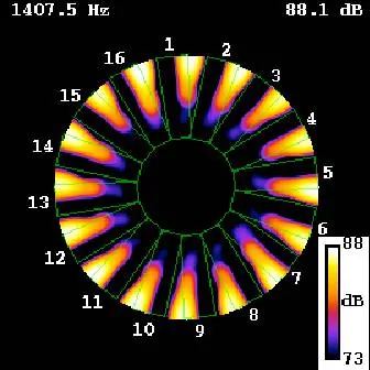
To capture sound patterns inside revolving engine fans, NASA Glenn researchers developed the Rotating Rake Mode Measurement System during the 1990s. Fixed microphones cannot resolve the rotating acoustic modal content of engine tones, which needs probes that rotate with the acoustic field. Engineers deployed rotating microphone rakes in the Advanced Noise Control Fan Rig, the 9- by 15-Foot Low Noise Wind Tunnel, and ground tests of full-scale turbofan engines. NASA GRC also built the Array48 phased array microphone system. By positioning microphones in one, two, or three-dimensional arrays, engineers pinpoint acoustic noise sources on scale-model jet flows, counter-rotating open rotor fans, and full-scale F404 military aircraft engines [2].
Noise reduction also depends on mapping airflow velocity around spinning blades. NASA researchers track airflow ahead of the propulsor, behind it, and between blades and stators using hotwire probes and Laser Doppler Velocimeters. Teams at NASA GRC also use particle image velocimetry and Raman spectroscopy to visualize flow disturbances that generate broadband noise. Velocity and acoustic datasets gathered during these NASA Glenn wind tunnel runs validate computational fluid dynamics predictions used to design noise-absorbing engine liners [2].
Instrumentation and Control in Academic Research
Academic universities treat instrumentation and control engineering as an interdisciplinary program combining electrical engineering, mechanical engineering, and computer systems. Degree coursework covers sensor principles, signal processing, robotics, and industrial communication protocols. Students complete laboratory projects to learn how automated systems function under real factory conditions. Vocational schools like the Northern Alberta Institute of Technology offer focused diplomas that train technicians to calibrate sensors, program logic controllers, and maintain industrial loops [6]. Technical training prepares workers for factory automation.
Scholarly progress in measurement science continues to receive academic honors. In October 2026, the journal Instrumentation highlighted studies on fault diagnosis in industrial systems and precision measurement advances marking the 130th anniversary of Tianjin University. The journal reported that editorial board member Yuen Ka Veng, Distinguished Professor in the Faculty of Science and Technology at the University of Macau, won the 15th Guanghua Engineering Science and Technology Prize from the Chinese Academy of Engineering. The China Instrument and Control Society and CAST sponsored these initiatives [7].
Author Diksha P Gupta said that instrumentation and control engineering suits perfectionists because tiny measurement errors can cause plant shutdowns. Modern engineering programs integrate Internet of Things sensor arrays, embedded microcontrollers, and machine learning models with classical control loops. Students study digital filtering algorithms to detect sensor drift before hardware fails. This curriculum ensures graduates can design resilient control loops for automated plants [6].
Career Pathways in Factory Automation
In industrial facilities, instrumentation engineers handle the design, setup, calibration, and maintenance of measurement systems while programming logic controllers and tuning PID feedback loops to ensure stable output [4]. Technicians in this field, often designated under the overarching job title of Instrument Fitter, work with electricians and pipe fitters in complex production units. Plant managers prioritize safety compliance because undetected instrument failures cause production shutdowns, physical plant damage, and regulatory penalties, making reliable automatic interlocks essential for personnel protection [5].
Job opportunities for skilled automation engineers remain steady in chemical manufacturing, oil refineries, and municipal utilities. According to Glassdoor salary figures, an instrumentation engineer in the United States earns an average annual salary of around $80,000. Entry-level roles start near $60,000 per year, whereas experienced specialists earn more than $100,000 annually. Salaries run higher in petroleum extraction, where plant outages create substantial economic hazards. As industrial sites embrace robotics and digital sensing, the market for instrumentation and control professionals continues to grow worldwide [4].
- ACADEMIC JOURNAL Wildhack, W. A. (1954). Instrumentation—Revolution in Industry, Science, and Warfare. Science, 120(3121), 15A. [Article Link]
- REPORT Koch, L. D., & Koppitch, A. (2026). Acoustics Instrumentation. NASA Glenn Research Center. [Article Link]
- WEBSITE Wikimedia Foundation. (2002). Instrumentation. Wikipedia. [Article Link]
- WEBSITE Automation Community. (2023). What is Instrumentation? Purpose, Career, Salary, Skills. Automation Community. [Article Link]
- WEBSITE Reddy, S. B. (2015). What is Instrumentation and Control Engineering? Instrumentation Tools. [Article Link]
- WEBSITE Wikimedia Foundation. (2014). Instrumentation and Control Engineering. Wikipedia. [Article Link]
- ACADEMIC JOURNAL Zu, J., Yang, J., & Dai, K. (2026). Current Issue: Instrumentation. China Instrument and Control Society. [Article Link]
APA 7: PerEXP Teamworks. (2026). Instrumentation and Control Drive Industrial and Flight Systems. PerEXP Teamworks.


