





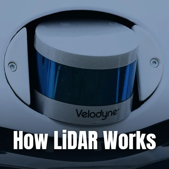
Understanding how lidar works begins with a simple optical principle: a sensor emits rapid laser pulses toward an object and records the exact time needed for the reflected light to bounce back to its receiver. Because light moves through air at a known, constant speed of roughly 299,792 kilometers per second, the measured travel time reveals the distance to each reflecting point with accuracy down to a few centimeters. When an instrument repeats this firing sequence hundreds of thousands or even millions of times every second across an environment, it gathers a dense collection of spatial coordinates known as a point cloud [10]. Rather than capturing a flat, two-dimensional picture like a conventional digital camera, light detection and ranging calculates true three-dimensional geometry across trees, roadway corridors, urban buildings, and planetary surfaces [14].
- The Core Principle Behind Laser Ranging
- How LiDAR Works to Calculate Surface Distances
- What Is Inside a Complete Sensor System?
- Comparing Time-of-Flight and Phase-Shift Scanning
- Mechanical Versus Solid-State Hardware Designs
- How Point Clouds Turn into Terrain Models
- How LiDAR Works in Autonomous Navigation
- Forestry, Atmosphere, and Space Applications
The Core Principle Behind Laser Ranging
The physical foundation of laser ranging traces back to early optical experiments that followed the invention of the laser in 1960. Under the direction of Malcolm Stitch, engineers at Hughes Aircraft Company built the first functioning system in 1961 to track satellites by timing coherent light pulses. That early hardware was called Colidar, an acronym combining coherent light detection and ranging. In 1963, developers produced the Colidar Mark II, a rifle-like ground rangefinder that reached targets 11 kilometers away with an accuracy of 4.5 meters [17].
At the center of every ranging calculation sits a straightforward distance equation, expressed mathematically as d = c × t / 2, where c represents the speed of light, t is the elapsed two-way travel time, and the division by two accounts for the outbound and return path of each emitted photon [17]. Because photons travel roughly 300,000 kilometers per second, a pulse striking an obstacle 15 meters away returns to the detector in approximately one hundred nanoseconds [10]. High-speed timing electronics record these minute intervals with picosecond precision, allowing modern instruments to resolve range differences within two to five centimeters [14]. When paired with calibrated angular sensors that measure mirror deflection or beam azimuth, each round-trip pulse yields a discrete spatial coordinate defined by three-dimensional X, Y, and Z positions [10].
Laser ranging also measures the amplitude of the returned signal, an attribute recorded as intensity. Highly reflective surfaces like light concrete return a higher fraction of light energy than dark asphalt [14]. This contrast helps automated software identify road markings and building materials.
How LiDAR Works to Calculate Surface Distances
Explaining how lidar works when evaluating varied terrain involves tracking how laser energy interacts with different physical surfaces. Unlike radar systems that emit wide radio waves or sonar devices that rely on acoustic pulses traveling slowly through water, an optical sensor sends focused beams of near-infrared or visible photons into the air [13]. These pulses travel in straight lines with minimal beam divergence, allowing the system to isolate small targets that would blend into background clutter under broader radar illumination [7]. Active illumination also means the equipment functions reliably during midnight surveys or in shadowed mountain ravines [12].
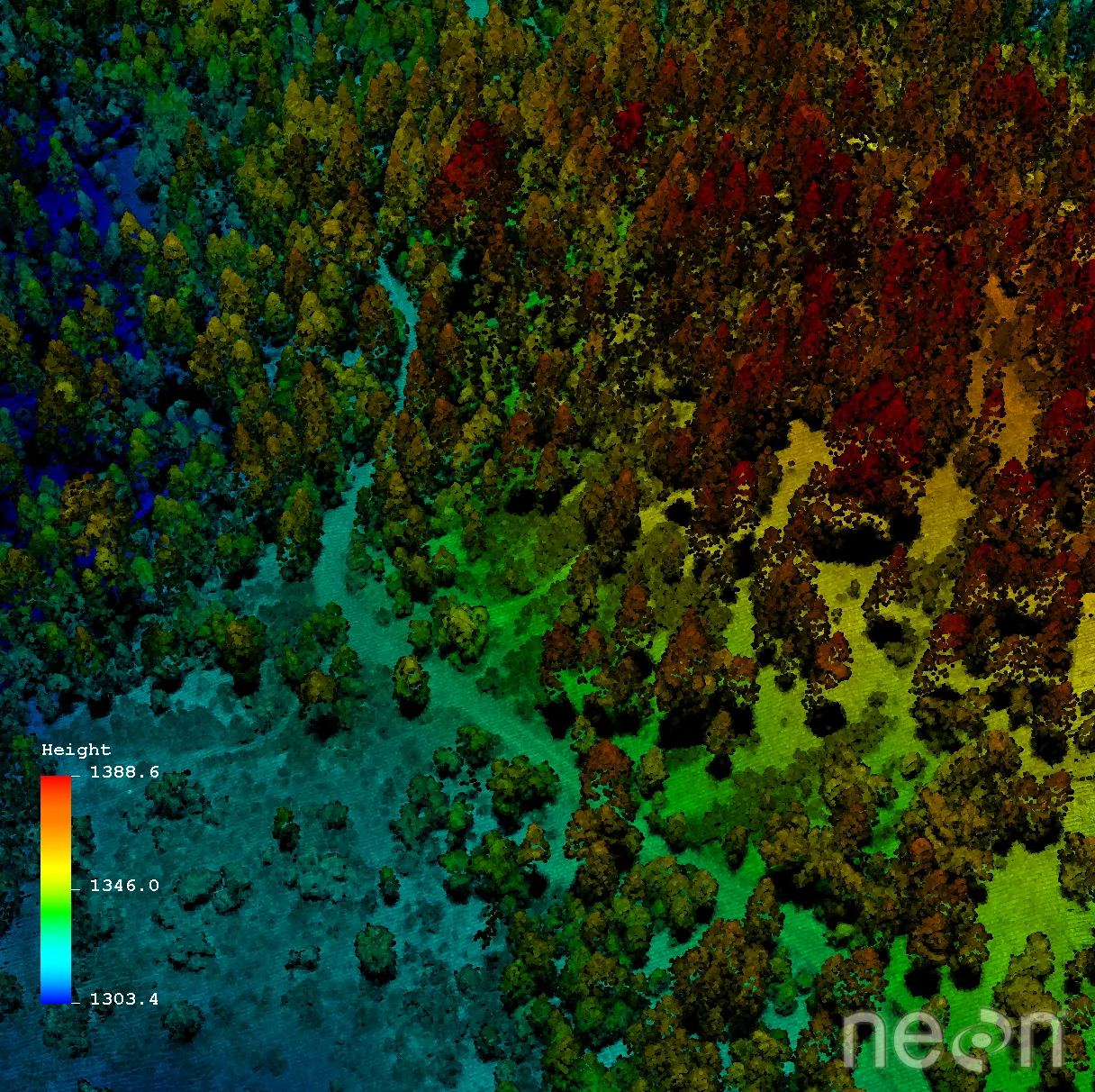
When an airborne pulse strikes a vegetated canopy, the light does not simply stop at the uppermost leaves. Part of the light energy bounces off the highest branches to form an initial reflection, often called the first return, while remaining photons slip through gaps in foliage to strike lower limbs or understory brush. The final photons reach bare soil or rock, creating a distinct last return that reveals ground elevation [16]. Systems capable of recording multiple returns per pulse can document between one and eleven individual reflections from a single outgoing flash, separating tree crowns from forest floor topography [11].
Full waveform sensors record the continuous distribution of returned energy rather than isolated peaks. The resulting energy profile reveals detailed branch density and understory vegetation structure [11]. Scientists use this waveform data to calculate biomass and canopy volume.
What Is Inside a Complete Sensor System?
A complete sensor system contains four primary hardware elements: a laser transmitter, beam-steering optics, a sensitive photodetector, and high-precision timing electronics. The transmitter generates light bursts through semiconductor diodes, relying on vertical-cavity surface-emitting lasers or edge-emitting lasers that fire at repetition frequencies exceeding hundreds of kilohertz [14]. To build accurate geospatial datasets from moving aircraft, engineers integrate these optical assemblies with satellite positioning receivers and an inertial measurement unit [1].
Mobile mapping platforms require constant spatial referencing because an aircraft or survey van pitches and rolls across uneven terrain. While onboard clocks track pulse emission down to sub-nanosecond intervals, an integrated inertial measurement unit monitors roll, pitch, and yaw angles at high sampling frequencies [11]. Position coordinates tie directly into satellite networks, where GPS technology and satellite clocks calculate location across flight trajectories. Combining real-time trajectory readings with instantaneous mirror angles ensures that every recorded return receives accurate geographic latitude, longitude, and elevation coordinates [1].
Photodetectors convert incoming photons into electrical current. Short-range systems operating at 905 nanometers generally use silicon avalanche photodiodes, which multiply incoming electrons like miniature radiation counters [13]. High-power 1550-nanometer systems require indium gallium arsenide detectors [14]. These infrared detector chips cost more but tolerate higher optical energy.
Comparing Time-of-Flight and Phase-Shift Scanning
Surveyors choose between two distinct laser measurement methods depending on operational range and required measurement speed. Time-of-flight devices emit short, high-energy pulses and track elapsed travel time directly, maintaining reliable signal returns across distances exceeding 350 meters in outdoor environments [10]. This method powers long-range terrain mapping, airborne forestry surveys, and vehicle collision avoidance where maximum range matters most [12].
Phase-shift scanners take a different path by transmitting a continuous, amplitude-modulated laser beam and analyzing the phase difference between outgoing and returning sine waves. By measuring wave displacement rather than discrete pulse flight intervals, phase-shift equipment achieves high measurement rates and millimeter-level accuracy at distances under 150 meters. Instruments such as the Trimble X12 capture up to 2.187 million points per second with a published point accuracy of 2.2 millimeters at twenty meters. Architectural preservation teams use phase-shift units on stationary tripods to record intricate interior moldings and industrial piping [10].
Each method presents practical tradeoffs. Phase-shift systems collect millions of measurements in minutes but lose signal coherence over extended outdoor ranges. Time-of-flight instruments tolerate dust and distance better. Modern surveying hardware often combines both approaches to balance speed with long-range outdoor performance [10].


Mechanical Versus Solid-State Hardware Designs
The physical arrangement of scanning components determines sensor durability, production expense, and vehicle integration options. Early commercial systems developed by Velodyne Lidar relied on spinning cylinders that housed stacked laser diodes and paired optical receivers [6]. In 1983, David Hall founded Velodyne as an audio company before developing laser scanners for the 2007 DARPA Grand Challenge. His spinning 64-laser unit produced roughly one million data points per second, providing five finisher vehicles with continuous 360-degree environmental awareness [18].
While spinning mechanical turrets provide complete panoramic coverage from vehicle roof racks, their moving parts face vibration wear and high assembly costs that restrict broad automotive adoption. Solid-state architectures eliminate large spinning assemblies by steering laser energy electronically or through micro-electromechanical systems [7]. Microscopic MEMS mirrors tilt quickly on silicon hinges to direct beams across target scenes, lowering unit weight and manufacturing complexity [14]. Other designs adopt flash illumination, flooding the field of view with a single laser pulse to capture an entire scene on a focal-plane array like a camera shutter. In research labs, optical phased arrays use wave interference to redirect light without any physical motion at all [7].
Component consolidation accelerated in February 2023 when Ouster and Velodyne completed an all-stock merger to unite their patent portfolios and supply chains [7]. The combined business retained Ouster as its corporate name while integrating digital semiconductor chips that house dozens of lasers on single silicon wafers. Consolidating lasers onto silicon chips lowers manufacturing costs for industrial robots and driverless vehicles [6].
How Point Clouds Turn into Terrain Models
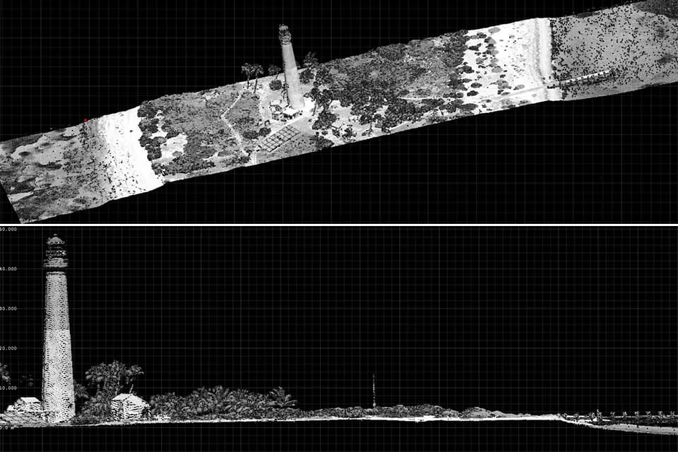
Raw data collected during a survey arrives as an unorganized point cloud containing millions of spatial coordinates [12]. Processing software cleans these collections by filtering anomalous reflections caused by airborne dust, low-flying birds, or electronic sensor noise [15]. Analysts then run automated classification algorithms that evaluate relative heights, geometric surface patterns, and return intensity to assign labels such as ground, high vegetation, water, or building roofs [16].
Classified points allow cartographers to generate standardized raster products that serve geographic information systems [1]. A digital surface model, or DSM, captures the uppermost envelope of the landscape, incorporating tree canopies, power transmission lines, and residential rooftops from first returns. In contrast, a digital terrain model strips away artificial structures and plant growth, interpolating only ground returns to reveal bare-earth topography. Subtracting a digital terrain model from a digital surface model produces a canopy height model, which isolates absolute vegetation height without elevation distortion from underlying hills [16].
Survey datasets are stored using the standard .las binary format established by the American Society of Photogrammetry and Remote Sensing. Martin Isenberg later created the open .laz format to provide lossless compression for massive spatial files. These formats preserve coordinate geometry, intensity values, and classification flags for engineers and environmental planners [11].
How LiDAR Works in Autonomous Navigation
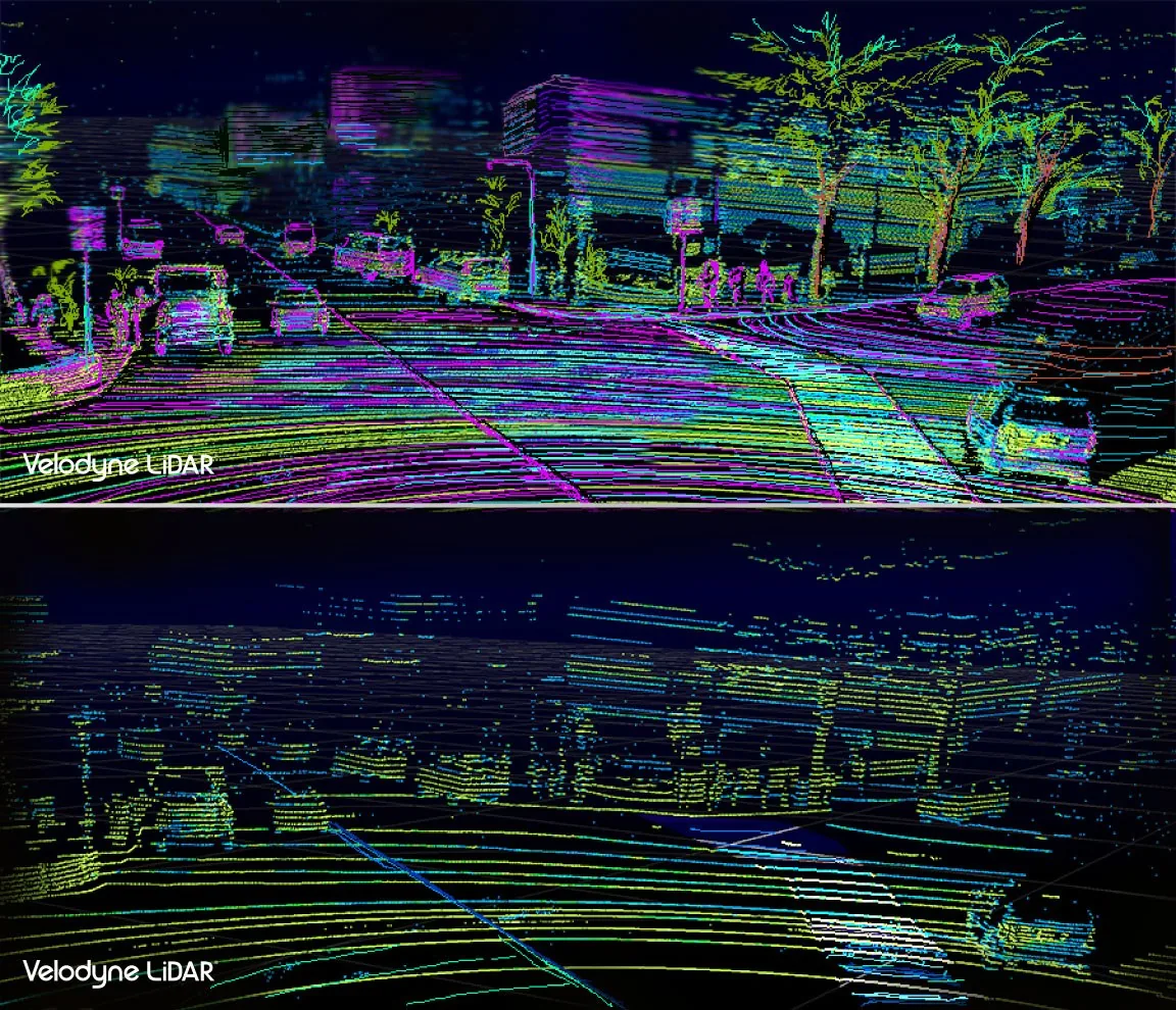
Self-driving vehicles rely on optical scanning to build an active spatial envelope around their chassis in real time [14]. Automotive sensors typically measure surrounding geometry with distance accuracy within plus or minus two centimeters, giving onboard computers far tighter localization than consumer satellite navigation, which drifts by several meters near tall city buildings. On suburban testing routes, arrays such as the Velodyne HDL-32E fire roughly 700,000 pulses per second to detect curbs, pedestrians, lane markings, and nearby vehicles. By comparing live point clouds against pre-mapped 3D street models, the vehicle determines its exact position on the road [8].
Sensor wavelength plays a central role in automotive perception and safety design. Standard 905-nanometer lasers use low-cost silicon chips, but their emission power must be capped to prevent retinal injury in pedestrians. In contrast, 1550-nanometer light is absorbed by the human eye’s cornea and lens before reaching the retina, allowing systems to project higher optical power. This higher power extends detection ranges beyond 250 meters, giving vehicles travelling at highway speeds several seconds of extra reaction time to brake or change lanes [14]. Anand Gopalan, former chief technology officer at Velodyne, said higher resolution sensors allow driving systems to categorize road debris directly without needing complex camera fusion [9].
Automotive engineers combine laser scanners with cameras and radar to achieve perception redundancy. Cameras read speed signs and traffic signal colors, while radar pierces dense fog and heavy rainfall [14]. Laser scanners provide the precise physical volume and shape of obstacles.
Forestry, Atmosphere, and Space Applications
Beyond highway navigation, optical remote sensing drives valuable discoveries across natural ecosystems and atmospheric physics [13]. In a study published in Remote Sensing, researchers Jonathon Donager, Andrew Sánchez Meador, and Ryan Blackburn compared forest measurements taken from fixed-wing aircraft, stationary tripods, and handheld mobile scanners in northern Arizona. Mobile laser scanning provided high structural accuracy at tree and plot scales, recording a mean absolute error for tree diameter of 4.8 centimeters compared to 9.1 centimeters for airborne scanning. Sánchez Meador said handheld tools work well among trees and make communicating forestry findings easier [5].
Atmospheric scientists use lidar instruments to measure trace gases, ozone concentrations, cloud altitudes, and aerosol layers from the ground to the upper stratosphere [4]. The European Aerosol Research Lidar Network operates 27 stations hosting over 44,000 profiles to monitor particulate pollution and volcanic ash clouds across Europe. Ground systems send polarized laser beams upward; when light bounces back, researchers calculate a linear depolarization ratio, denoted by δ, to distinguish spherical water droplets from irregularly shaped ice crystals [19]. Other installations, such as differential absorption lidar, measure trace atmospheric gases by tracking wavelength-dependent absorption [4].
Space agencies also mount laser instruments on exploratory probes, a practice that began in 1971 when Apollo 15 mapped lunar craters with an orbital laser altimeter [17]. Similar technology helped steer the Ingenuity helicopter during its exploratory flights over the surface of Mars [15]. Today, projects like the NASA CASALS instrument maps 3D landscapes without moving mirrors, demonstrating how solid-state laser steering improves planetary exploration. By calculating precise approach distances and mapping surface hazards, descending spacecraft land safely on rugged celestial bodies [2].
- WEBSITE National Oceanic and Atmospheric Administration. (2012). What is LIDAR. National Ocean Service. [Article Link]
- CONFERENCE PAPER Amzajerdian, F., Pierrottet, D. F., Petway, L. B., Hines, G. D., & Roback, V. E. (2011). Lidar Systems for Precision Navigation and Safe Landing on Planetary Bodies. International Symposium on Photoelectronic Detection and Imaging. [Article Link]
- REPORT NASA Airborne Science Program. (2017). Lidar. [Article Link]
- WEBSITE NOAA Chemical Sciences Laboratory. Atmospheric Remote Sensing: Instruments. [Article Link]
- ACADEMIC JOURNAL Donager, J. J., Sánchez Meador, A. J., & Blackburn, R. C. (2021). Adjudicating Perspectives on Forest Structure: How Do Airborne, Terrestrial, and Mobile Lidar-Derived Estimates Compare?. Remote Sensing, 13(12), 2297. [Article Link]
- ONLINE NEWS Lee, T. B. (2020). Lidar Is Finally Becoming a Real Business. WIRED. [Article Link]
- ONLINE NEWS Rosevear, J. (2023). Lidar makers Ouster and Velodyne complete their merger, creating a sector powerhouse. CNBC. [Article Link]
- ONLINE NEWS Cunningham, W. (2016). How lasers map the world for self-driving cars. CNET. [Article Link]
- ONLINE NEWS Popper, B. (2017). Velodyne’s latest LIDAR lets driverless cars handle high-speed situations. The Verge. [Article Link]
- WEBSITE THE FUTURE 3D. (2026). How Does LiDAR Work? A Complete Explanation. [Article Link]
- WEBSITE Wasser, L. A. (2026). The Basics of LiDAR – Light Detection and Ranging – Remote Sensing. NEON Science. [Article Link]
- WEBSITE Lidarvisor. (2026). What Is LiDAR? Definition, How It Works and Uses. [Article Link]
- WEBSITE Woodford, C. (2023). LIDAR: a simple introduction. Explain that Stuff. [Article Link]
- WEBSITE HowAtlas. (2026). How LiDAR Works: A Complete Technical Guide to 3D Laser Scanning. [Article Link]
- WEBSITE IBM. (2023). What is LiDAR?. IBM Think. [Article Link]
- WEBSITE OpenTopography. (2000). What is Lidar?. [Article Link]
- WEBSITE Wikipedia contributors. Lidar. Wikipedia, The Free Encyclopedia. [Article Link]
- WEBSITE Wikipedia contributors. Velodyne Lidar. Wikipedia, The Free Encyclopedia. [Article Link]
- WEBSITE Wikipedia contributors. Atmospheric lidar. Wikipedia, The Free Encyclopedia. [Article Link]


